
PULSAR PowerPoint PPT Presentation
1 / 3
Title: PULSAR
1
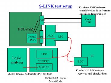
S-LINK test setup
Kristians VME software - reads/writes data
from/to RAM - initiates data transfer
PULSAR
Crate CPU
VME
AUX
P3
LSC
Control FPGA
PC
Logic analyzer
LDC
LDC
SLITEST
SLIDAD
Kristians S-LINK software - receives and checks
data
checks data received with S-LINK test tools
2
S-LINK Tx firmware
- first version
S-LINK interface
dataout to LSC
CDF L1A
control signals to LSC
VMEL1A
R A M
mif file
512 words deep
0 1B0F00000 1 000000020
2 000000030 3 000000040
4 000000050 5 000000060 6
000000070 7 000000080 8
000000090 9 000000100 10
EE0F00000
VME interface
data in
data out
- control S-LINK interface
- to start transmitting data
- - write and read RAM
3
Features to be added
- S-LINK input from AUX card (L2 trigger decision)
- currently working on this
- Measuring time between sending one event and
receiving L2 trigger decision
Starts clock - starts sending data
PULSAR
PC algorithm
one event worth of data
L2 trigger decision (128bits)
Stops clock - L2T decision
received
Recommended
