
MultiMEMS MPW Design Introduction Course Part 2 PowerPoint PPT Presentation
1 / 22
Title: MultiMEMS MPW Design Introduction Course Part 2
1
MultiMEMS MPW Design Introduction CoursePart 2
- Process Description - Part I
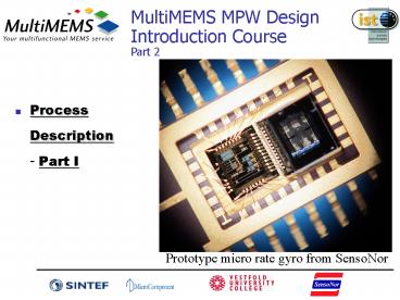
Prototype micro rate gyro from SensoNor
2
Contents
- Process Description, Part I
- Cross section overview
- Key process features
- MPW process step-by-step
- Process Description, Part II
- Absolute limitations
- Process monitors
- Test data
3
Cross section overview
4
Feature 1 Buried Piezo-resistors
- Buried under epi-layer
- Used for long-term stability
- Sheet resistivity ca. 500 W/
- Cannot be used in epi-thick membrane
5
Feature 2 Surface Piezo-resistors
- Diffused into epi-layer surface
- Offers highest sensitivity
- Sheet resistivity ca. 800 W/
- Particularly suited on springs
6
Feature 3.1 Buried conductors
- Under epi-layer
- Contact to buried resistor
- Used for crossing anodic bonding area (top glass
will not bond directly onto surface features)
7
Feature 3.2 Surface conductors
- Implanted in epi-layer surface
- used to contact surface resistors and buried
conductors or as ordinary interconnects
8
Feature 4Wet Backside etch
- Electro-chemical etch-stop allows 3 different
thicknesses - full-wafer thickness (400 mm)
- e.g. heavy seismic masses
- epi-layer thickness (3 mm)
- thin membrane, springs
- n-well thickness (23 mm)
- thick membranes, masses, bosses,
9
Feature 5Dry Release Etch
- Allows moving structures
- Gas/fluid flow through wafer
- Through epi-thick membranes only
- cuts through 6 mm thick Si
10
Feature 5 Dry Release Etch
- Recesses/channels
- allowed design rule violation, 10 mm depth, not
guaranteed
11
Feature 6.1 Top Glass
- Single-sided structuring of top glass for
- Reference cavity formation
- Bond-pad area
- Allow movement of structures
- Gas/fluid channels
12
Feature 6.2 Bottom Glass
- Double-sided structuring (through-wafer wet etch)
of bottom glass - Used e.g. as pressure inlet
- Single side cavity possible
13
Feature 6.3 Glass bonding
- Triple-stack anodic bonding offers
- added functionality
- Reference cavity pressure
- Damping
- Overforce protection
- micro-encapsulation
- Media protection of front-side
- More robust handling
- Less package-stress sensitive
14
Overview of process
15
MPW Process (1)
- NOWEL
- n impl. diff.
- BUCON
- p impl. diff.
16
MPW Process (2)
- BURES
- p impl. diff.
- n epi
17
MPW Process (3)
- TIKOX
- 2 oxidations
- SUCON
- p impl. diff.
18
MPW Process (4)
- SURES
- p impl.
- NOSUR
- n impl. diff
19
MPW Process (5)
- COHOL
- oxide etch
- MCOND
- Al sputter pattern
20
MPW Process (6)
- BETCH
- TMAH etch
- NOBOA
- oxide etch
- RETCH
- dry etch
21
MPW Process (7)
- TOGE BOGEF BOGEB
- wet etching of glass anodic bonding
- Dicing
22
Process Description
- End of this Chapter
- Questions or Comments?
Recommended
