
Experiment 3 PowerPoint PPT Presentation
Title: Experiment 3
1
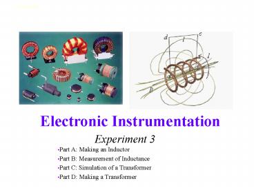
Experiment 3
- Part A Making an Inductor
- Part B Measurement of Inductance
- Part C Simulation of a Transformer
- Part D Making a Transformer
2
Review RLC and Resonance
- How can the transfer function be greater than 1?
- At resonance, impedance value is a minimum
- At resonance, impedance of inductor and capacitor
cancel each other out (equal in magnitude, phase
is opposite) - So circuit is purely resistive at resonance
- H depends on the position of Vout
http//ecow.engr.wisc.edu/cgi-bin/getbig/ece/271/a
llie/labmanuals/1271l1sp03.doc
3
Review RLC and Resonance
http//ecow.engr.wisc.edu/cgi-bin/getbig/ece/271/a
llie/labmanuals/1271l1sp03.doc
4
Inductors Transformers
- How do transformers work?
- How to make an inductor?
- How to measure inductance?
- How to make a transformer?
?
5
Part A
- Inductors Review
- Calculating Inductance
- Calculating Resistance
6
Inductors-Review
- General form of I-V relationship
- For steady-state sine wave excitation
7
Determining Inductance
- Calculate it from dimensions and material
properties - Measure using commercial bridge (expensive
device) - Infer inductance from response of a circuit. This
latter approach is the cheapest and usually the
simplest to apply. Most of the time, we can
determine circuit parameters from circuit
performance.
8
Making an Inductor
- For a simple cylindrical inductor (called a
solenoid), we wind N turns of wire around a
cylindrical form. The inductance is ideally given
by - where this expression only holds when the
length d is very much greater than the diameter
2rc
9
Making an Inductor
- Note that the constant ?o 4? x 10-7 H/m is
required to have inductance in Henries (named
after Joseph Henry of Albany) - For magnetic materials, we use ? instead, which
can typically be 105 times larger for materials
like iron - ? is called the permeability
10
Some Typical Permeabilities
- Air 1.257x10⁻⁶ H/m
- Ferrite U M33 9.42x10⁻⁴ H/m
- Nickel 7.54x10⁻⁴ H/m
- Iron 6.28x10⁻³ H/m
- Ferrite T38 1.26x10⁻² H/m
- Silicon GO steel 5.03x10⁻² H/m
- supermalloy 1.26 H/m
11
Making an Inductor
- If the coil length is much smaller than the
diameter (rw is the wire radius) - Such a coil is used in the
- metal detector at the right
Form Diameter 2rc
Coil Length (d)
12
Calculating Resistance
- All wires have some finite resistance. Much of
the time, this resistance is negligible when
compared with other circuit components. - Resistance of a wire is given by
- l is the wire length
- A is the wire cross sectional area (prw2)
- s is the wire conductivity
13
Some Typical Conductivities
- Silver 6.17x10⁷ Siemens/m
- Copper 5.8x10⁷ S/m
- Aluminum 3.72x10⁷ S/m
- Iron 1x10⁷ S/m
- Sea Water 5 S/m
- Fresh Water 25x10-6 S/m
- Teflon 1x10-20 S/m
- Siemen 1/ohm
14
Wire Resistance
- Using the Megaconverter at http//www.megaconverte
r.com/Mega2/ - (see course website)
15
Part B Measuring Inductance with a Circuit
- For this circuit, a resonance should occur for
the parallel combination of the unknown inductor
and the known capacitor. If we find this
frequency, we can find the inductance.
16
In Class Problem 1
Vout
Vin
- What is ZLC (assuming R2 is very small)?
- What does R2 represent?
- What is its transfer function (equation)?
- What is H at low and high frequencies?
- What is H at the resonant frequency, ?0?
17
Determining Inductance
Vout
Vin
- ReminderThe parallel combination of L and C goes
to infinity at resonance. (Assuming R2 is small.)
18
Determining Inductance
19
(No Transcript)
20
- Even 1 ohm of resistance in the coil can spoil
this response somewhat
Coil resistance small
Coil resistance of a few Ohms
21
Part C
- Examples of Transformers
- Transformer Equations
22
Transformers
- Cylinders (solenoids)
- Toroids
23
Transformer Equations
Symbol for transformer
24
Deriving Transformer Equations
- Note that a transformer has two inductors. One is
the primary (source end) and one is the secondary
(load end) LS LL - The inductors work as expected, but they also
couple to one another through their mutual
inductance M2k2 LS LL
25
Transformers
- Assumption 1 Both Inductor Coils must have
similar properties same coil radius, same core
material, and same length.
26
Transformers
IS
IL
Note Current Direction
- Let the current through the primary be
- Let the current through the secondary be
- The voltage across the primary inductor is
- The voltage across the secondary inductor is
27
Transformers
- Sum of primary voltages must equal the source
- Sum of secondary voltages must equal zero
28
Transformers
- Assumption 2 The transformer is designed such
that the impedances are much
larger than any resistance in the circuit. Then,
from the second loop equation
29
Transformers
- k is the coupling coefficient
- If k1, there is perfect coupling.
- k is usually a little less than 1 in a good
transformer. - Assumption 3 Assume perfect coupling (k1)
- We know M2k2 LS LL LS LL and
- Therefore,
30
Transformers
- The input impedance of the primary winding
reflects the load impedance. - It can be determined from the loop equations
- 1
- 2
- Divide by 1 IS. Substitute 2 and M into 1
31
Transformers
- Find a common denominator and simplify
- By Assumption 2, RL is small compared to the
impedance of the transformer, so
32
Transformers
- It can also be shown that the voltages across the
primary and secondary terminals of the
transformer are related by - Note that the coil with more turns has the
larger voltage. - Detailed derivation of transformer equations
- http//hibp.ecse.rpi.edu/connor/education/transfo
rmer_notes.pdf
33
Transformer Equations
34
In Class Problem 2
NsNL
VGEN120V RL20 O NL1 NS12
Vs
VL
VGEN
- 1. Find VL if RS0
- Find VL if Rs 1 k O
- Hint Is VGEN VS? Under what conditions is this
not true? How would you find VS? Need Zin
Is
Vs
VL
Zin
35
Part D
- Step-up and Step-down transformers
- Build a transformer
36
Step-up and Step-down Transformers
- Step-up Transformer
Step-down Transformer
Note that power (PVI) is conserved in both
cases.
37
Build a Transformer
- Wind secondary coil directly over primary coil
- Try for half the number of turns
- At what frequencies does it work as expected with
respect to voltage? When is ?L gtgt R?
38
Some Interesting Inductors
- Induction Heating
39
Some Interesting Inductors
- Induction Heating in Aerospace
40
Some Interesting Inductors
- Induction Forming
41
Some Interesting Inductors
- Coin Flipper
- Flash camera circuits charge 6 capacitors
- Large current in primary coil
- Large current induced in coin (larger by ratio of
turns) - Current in coin creates electromagnet of opposite
polarity (Repel!)
42
Some Interesting Inductors
- GE Genura Light
43
Some Interesting Transformers
- A huge range in sizes
44
Household Power
- 7200V transformed to 240V for household use
45
Wall Warts
Transformer
46
In Class Problem 1
Vout
Vin
- What is ZLC (assuming R2 is very small)?
- What does R2 represent?
- What is its transfer function (equation)?
- What is H at low and high frequencies?
- What is H at the resonant frequency, ?0?
47
In Class Problem 1
Vout
Vin
48
In Class Problem 1
Vout
Vin
49
In Class Problem 1
- What is H at low frequencies?
- This can be determined from the magnitude so
- Remember these steps!
- Take the lowest power in the numerator and
denominator of the equation - Write down x1, y1, x2, and y2 (can do this in
your head) - Use the magnitude equation (square and square
root numerator and denominator) - Simplify (this is the answer if approaching 0)
- Take limit as it approaches 0 (this is the answer
at 0)
50
In Class Problem 1
- What is H at low frequencies?
- Step 1 Take lowest power in numerator and
denominator - Step 2 Find x1, y1, x2, y2
51
In Class Problem 1
- What is H at low frequencies?
- Step 3 Use the magnitude equation
- Step 4 Simplify
- Step 5 Take limit as ? approaches 0
- Answer is that it becomes very small or 0
52
In Class Problem 1
- What is H at high frequencies?
- This can be determined from the magnitude so
- Remember these steps!
- Take the highest power in the numerator and
denominator of the equation - Write down x1, y1, x2, and y2 (can do this in
your head) - Use the magnitude equation (square and square
root numerator and denominator) - Simplify (this is the answer if approaching 8)
- Take limit as it approaches 0 (this is the answer
at 8)
53
In Class Problem 1
- What is H at high frequencies?
- Step 1 Take highest power in numerator and
denominator - Step 2 Find x1, y1, x2, y2
54
In Class Problem 1
- What is H at high frequencies?
- Step 3 Use the magnitude equation
- Step 4 Simplify
- Step 5 Take limit as ? approaches 8
- Answer is that it becomes very small or 0
55
In Class Problem 1
- What is H at the resonant frequency, ?0?
56
In Class Problem 2
57
In Class Problem 2
Recommended
