
Frequency Domain Analysis PowerPoint PPT Presentation
1 / 32
Title: Frequency Domain Analysis
1
Frequency Domain Analysis
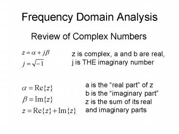
Review of Complex Numbers
z is complex, a and b are real, j is THE
imaginary number
a is the real part of z b is the imaginary
part z is the sum of its real and imaginary parts
2
Complex Numbers
A complex number may be represented by plotting
it in rectangular coordinates
b
a
Or, in polar coordinates
3
Complex Numbers
From this, It's obvious that
b
a
4
Complex Numbers
Titans Formula
Eulers Formula
Oilers Formula
So, multiplying by the magnitude of z
So another way of writing the complex number z is
5
Complex Arithmetic
For addition of complex numbers, use the
rectangular form
For multiplication, you can still use the
rectangular form
But polar form is often more convenient
6
Complex Arithmetic
Every complex number
has its complex conjugate
In polar form
7
Complex Arithmetic
Again, for division, the polar form is often more
convenient
But, the rectangular form can be used
8
Complex Functions
Suppose z is a complex-valued function of a real
valued variable f
Its real and imaginary parts are real-valued
functions of f, as are its magnitude and phase
9
Frequency Response
The response of a BIBO stable, LSI system to a
sinusoidal input is of particular interest,
because any periodic signal may be described as a
sum of sinusoids (Fourier series) and any
aperiodic signal can be described as an integral
of a continuum of sinusoids. The response of
such a system to a single sinusoid is a sinusoid
of the same frequency. The amplitude and phase
of the steady-state response are functions of the
frequency, and comprise the systems Frequency
Response.
10
Frequency Response
Consider a sinusoidal signal
This can be represented as a phasor
We can find the response of a system H(s) to V
11
Frequency Response
Remember our old friend, the RC lowpass filter?
12
Frequency Response
Substituting j2pf for s
H(f) is a complex-valued function of the
real-valued variable, f. It has a real part and
an imaginary part, as well as a magnitude and
phase angle. The magnitude is the systems
Amplitude Response, and the phase angle is its
Phase Response.
13
Frequency Response
For a frequency f, we can find the output phasor
Or, in the time domain,
14
Frequency Response
For our RC circuit,
So
15
Frequency Response
If our filter is normalized, that is, has a
corner frequency such that
16
Frequency Response
Wed probably like to see plots of the frequency
response
17
Frequency Response
18
Negative Frequency
What???
This is nice. The real part is fine, but what
does an imaginary sinusoid look like on an
oscilloscope? What does it sound like? It would
be nice if we could just get rid of it.
19
Negative Frequency
Adding these
Which can be rewritten
20
Negative Frequency
So the real sinusoid can be thought of as a sum
of two complex exponentials, one of positive
frequency and one of negative frequency. Any
real-world signal, whether it is a
single-frequency sinusoid or not, may also be
treated as having a positive frequency component
and a negative frequency component. This is
often referred to as a Mathematical Fiction.
21
Negative Frequency
We use this fiction because it is convenient.
Suppose we have a system H(f) driven by a complex
exponential
Then we can solve for the output signal by simply
multiplying the complex exponential input by H(f)
22
Negative Frequency
23
Negative Frequency
Recall that a real sinusoid can be written as a
sum of two complex exponentials, one of positive
frequency and one of negative frequency
Or
Where
24
Negative Frequency
So y(t) is an increasing function of t,
increasing at a constant rate f (or w).
Therefore, cos(t) can be represented by two
counterrotating vector, rotating at rates of w
and w.
25
Negative Frequency
26
Frequency Response and Impulse Response
If a system whose impulse response is h(t) is
driven by a signal x(t), where
Then the output signal can be found by
convolution
27
Frequency Response and Impulse Response
So,
The bracketed term is obviously the systems
frequency response, but on closer inspection it
is also the Fourier transform of the impulse
response.
28
Frequency Response
For example, take our old friend the RC lowpass
filter. We previously found its impulse response
to be
Lets plug this into the Fourier Transform
integral
29
Frequency Response
30
Frequency Response
This is the same result we got earlier, by
circuit analysis. The system frequency response
is the same as the Fourier transform of the
system impulse response.
31
Periodic Signals
Any periodic signal can be represented as a
Fourier series, or sum of sinusoids (or complex
exponentials).
Since were concerned only with linear systems,
the response to a sum of signals is the sum of
the responses to each individual signal
32
Periodic Signals
Note that this is the steady-state response, the
output that would be observed if the driving
signal had been present for a long time (strictly
speaking, since the Big Bang). In real life, the
response would also contain a component called
the Natural Response which would account for the
finite duration of the input.
Recommended
