
Testing Minimum Bias Trigger Scintillators with Cosmic Rays PowerPoint PPT Presentation
1 / 1
Title: Testing Minimum Bias Trigger Scintillators with Cosmic Rays
1
Trigger and DAQ for the J-Parc Experiment Anton
KapliySupervisor Professor Yau WahDepartment
of Physics, University of Chicago, Chicago, IL
60637
- Introduction
- We propose a design of Level-1 trigger and
readout chain for the upcoming J-Parc experiment
that supports trigger rates in excess of 100 KHz
with virtually no downtime. The design has been
implemented and tested on an Altera Stratix II
FPGA Development Kit.
- Digital Electronics in FPGA
- Impractical to save all ADC data at 125 Mhz
- Data Rate 570 gigabytes/second (!!!)
- Use trigger only save signals that pass energy
threshold - 100 KhZ trigger ? 5 megabytes/second
- This data must be pipelined before PC can read it
out - Accomplished in a Field Programmable Field Array
(FPGA) - Digital semiconductor device that can be
reprogrammed after it is manufactured. - Each FPGA serves 16 readout channels
- Work done in Altera Quartus II software
- VHDL, AHDL hardware description language
- Firmware uploaded through JTAG interface
- Stratix II DSP Development Board with a 3000
FPGA - On-board ADC and DAC to visualize signals
- Digital readout through a computer
- In the first test, we send 3 near-simultaneous
digital test-pulses - The board self-triggers and saves three events,
shown below
To verify that the FPGA is fast enough to
accommodate our clock rate, we run the entire
design at several clocks. Design was shown to
work well at 100 200 Mhz. Two test pulses
triggered and saved at 100 and 150 Mhz
Implementation
Robustness
LeCroy pulser
Scope
FPGA Dev't Board
Iteration of first pulse
Fig. 8. Different clocks
- Conclusions and follow-up
- The designed that we developed and implemented
appears to perform well under the expected timing
and trigger rate conditions. - However, a design that works on a Development
Board will not necessarily work on an actual DAQ
board due to different pin-out and presence of
extra logic (VME slave controller and G-link
interface). - Therefore, the ultimate test will be performed
later this year at a Fermilab test, by which
time the DAQ board will be designed.
Coax cables
Connected to PC via JTAG/USB
Fig. 1. Experimental setup
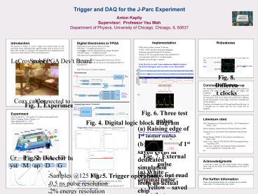
Fig. 6. Three test pulses (a) Raising edge of 1st
input pulse (b) Beginning of 1st saved event in
dedicated simulation (c) Same, but read from an
actual chip (d) All three saved events, digital
data w/ interpolation (e) Same, but shown on
scope via DAC Note small bump part of 2nd
pulse saved in 1st event
- Experiment
- Very rare decay KL?p0?? probes CP violation in
the quark sector - Flavor Changing Neutral Current s?d
- Major background KL?p0p0
- Must efficiently detect photons
- Literature cited
- Taku Yamanaku et al, Proposal for the KL?p0??
Experiment at JPARC, 2006 - Meson Summary Tables (Review of Particle
Physics), 2006 - Jiansen Ma et al, The Bessel Filter Simulation
(internal note), 2007 - Mircea Bogdan, JPARC-K DAQ System (presentation
at KEK), 2006 - Altera Corp., Stratix II DSP EP2S60 DSP
Development Board Data Sheet, 2006 - Altera Corp., Quartus II Development Software
Handbook v6.1 (Complete Five-Volume Set), 2005 - etc...
Fig. 4. Digital logic block diagram
Fig. 7. External pulse (a) White original
pulse Yellow saved event that underwent
ADC DAC (b) Saved event before DAC Note
on-board ADC is saturated before pulse reaches
max value. This explains larger platoe in the
saved event.
Fig. 2. Detector barrel.
Trigger threshold
- Acknowledgments
- I would like to thank Yau Wah, Harold Sanders,
Mircea Bogdan, Fukun Tang, and Jim Pilcher for
providing guidance in the course of this research.
Crystal
PMT
Shaper
FADC
FPGA
- Samples _at_125 Mhz
- 0.5 ns pulse resolution
- 2 energy resolution
Fig. 5. Trigger operation.
- For further information
- Please contact antonk_at_uchicago.edu. A detailed
report is available online at http//www.hep.uchic
ago.edu/antonk/.
Fig. 3. PMT shaper pulse
Recommended
