
7.5 Dictionarybased Coding PowerPoint PPT Presentation
1 / 27
Title: 7.5 Dictionarybased Coding
1
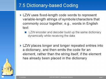
7.5 Dictionary-based Coding
- LZW uses fixed-length code words to represent
variable-length strings of symbols/characters
that commonly occur together, e.g., words in
English text - LZW encoder and decoder build up the same
dictionary dynamically while receiving the data - LZW places longer and longer repeated entries
into a dictionary, and then emits the code for an
element, rather than the string itself, if the
element has already been placed in the dictionary
2
LZW compression for string ABABBABCABABBA
- The output codes are 1 2 4 5 2 3 4 6 1. Instead
of sending 14 characters, only 9 codes need to be
sent (compression ratio 14/9 1.56).
3
LZW decompression (1 2 4 5 2 3 4 6 1)
ABABBABCABABBA
4
LZW Coding (contd)
- In real applications, the code length l is kept
in the range of l0, lmax. The dictionary
initially has a size of 2l0. When it is filled
up, the code length will be increased by 1 this
is allowed to repeat until l lmax - When lmax is reached and the dictionary is filled
up, it needs to be flushed (as in Unix compress,
or to have the LRU (least recently used) entries
removed
5
7.6 Arithmetic Coding
- Arithmetic coding is a more modern coding method
that usually out-performs Huffman coding - Huffman coding assigns each symbol a codeword
which has an integral bit length. Arithmetic
coding can treat the whole message as one unit - More details in the book
6
7.7 Lossless Image Compression
- Due to spatial redundancy in normal images I, the
difference image d will have a narrower histogram
and hence a smaller entropy
7
Lossless JPEG
- A special case of the JPEG image compression
- The Predictive method
- Forming a differential prediction A predictor
combines the values of up to three neighboring
pixels as the predicted value for the current
pixel
8
- 2. Encoding The encoder compares the prediction
with the actual pixel value at the position X
and encodes the difference using Huffman coding
9
Performance generally poor, 2-3
10
Implementation details for VLC
- Consider the code for HELLO 10 110 0 0 111. how
do you extract a bit? (decoding) - union bitField
- struct
- unsigned int one1
- unsigned int two1
- unsigned int thr1
- unsigned int fou1
- unsigned int fiv1
- unsigned int six1
- unsigned int sev1
- unsigned int eig1
- bit
- unsigned char chr
Bit operators One (0xb1 0x80)gtgt7
11
Chapter 8 Lossless compression
- Information is permanently lost in the
compression process to achieve higher compression
ratios - Metrics Mean square error, SNR, Peak SNR
- Primary loss mechanism quantization to reduce
the number of different levels in the input - Three different forms of quantization
- Uniform midrise and midtread quantizers
- Nonuniform companded quantizer (u-law, A-law)
- Vector Quantization
12
Transform coding
- The rationale behind transform coding
- If Y is the result of a linear transform T of the
input vector X in such a way that the components
of Y are much less correlated, then Y can be
coded more efficiently than X - If most information is accurately described by
the first few components of a transformed vector,
then the remaining components can be coarsely
quantized, or even set to zero, with little
signal distortion - Discrete Cosine Transform (DCT)
13
Spatial Frequency and DCT
- Spatial frequency indicates how many times pixel
values change across an image block - The DCT formalizes this notion with a measure of
how much the image contents change in
correspondence to the number of cycles of a
cosine wave per block - The role of the DCT is to decompose the original
signal into its DC and AC components the role of
the IDCT is to reconstruct (re-compose) the signal
14
Graphical Illustration of 8 8 2D DCT basis
15
Chapter 9 Image compression
- JPEG standard - JPEG is a lossy image compression
method. It employs a transform coding method
using the DCT (Discrete Cosine Transform) - An image is a function of i and j (or
conventionally x and y) in the spatial domain.
The 2D DCT is used as one step in JPEG in order
to yield a frequency response which is a function
F(u, v) in the spatial frequency domain, indexed
by two integers u and v
16
Observations for JPEG Image Compression
- The effectiveness of the DCT transform coding
method in JPEG relies on 3 major observations - Observation 1 Useful image contents change
relatively slowly across the image, i.e., it is
unusual for intensity values to vary widely
several times in a small area, for example,
within an 88 image block. - much of the information in an image is repeated
(spatial redundancy) - Observation 2 Psychophysical experiments suggest
that humans are much less likely to notice the
loss of very high spatial frequency components
than the loss of lower frequency components - spatial redundancy reduced by reducing the high
spatial frequency contents - Observation 3 Visual acuity (accuracy in
distinguishing closely spaced lines) is much
greater for gray (black and white) than for
color - chroma subsampling (420) is used in JPEG
17
JPEG encoder
18
DCT on image blocks
- Image is divided into 8 8 blocks. The 2D DCT is
applied to each block image f(i, j), with output
being the DCT coefficients F(u, v) for each block - Using blocks, however, has the effect of
isolating each block from its neighboring
context. This is why JPEG images look choppy
(blocky) when a high compression ratio is
specified by the user
19
Quantization
- F(u, v) represents a DCT coefficient, Q(u, v) is
a quantization matrix entry, and
represents the quantized DCT coefficients which
JPEG will use in the succeeding entropy coding - quantization step is the main source for loss in
JPEG - The entries of Q(u, v) tend to have larger values
towards the lower right corner. This aims to
introduce more loss at the higher spatial
frequencies a practice supported by
Observations 1 and 2 - default Q(u, v) values obtained from
psychophysical studies with the goal of
maximizing the compression ratio while minimizing
perceptual losses in JPEG images.
20
- The Luminance Quantization Table
- The Chrominance Quantization Table
16 11 10 16 24 40 51 61 12 12 14 19 26 58
60 55 14 13 16 24 40 57 69 56 14 17 22 29 51
87 80 62 18 22 37 56 68 109 103 77 24 35 55
64 81 104 113 92 49 64 78 87 103 121
120 101 72 92 95 98 112 100 103 99
17 18 24 47 99 99 99 99 18 21 26 66 99 99 99
99 24 26 56 99 99 99 99 99 47 66 99 99 99 99 99
99 99 99 99 99 99 99 99 99 99 99 99 99 99 99 99
99 99 99 99 99 99 99 99 99 99 99 99 99 99 99 99 99
21
515 65 -12 4 1 2 -8 5 -16 3 2 0 0 -11
-2 3 -12 6 11 -1 3 0 1 -2 -8 3 -4 2 -2
-3 -5 -2 0 -2 7 -5 4 0 -1 -4 0 -3 -1 0
4 1 -1 0 3 -2 -3 3 3 -1 -1 3 -2 5
-2 4 -2 2 -3 0 F(u, v)
22
(No Transcript)
23
Run-length Coding on AC coefficients
- To make it most likely to hit a long run of
zeros a zig-zag scan is used to turn the 88
matrix into a 64-vector
24
DPCM on DC coefficients
- The DC coefficients are coded separately from the
AC ones. Differential Pulse Code modulation
(DPCM) is the coding method - If the DC coefficients for the first 5 image
blocks are 150, 155, 149, 152, 144, then the DPCM
would produce 150, 5, -6, 3, -8, assuming di
DCi1 - DCi, and d0 DC0 - AC components are Huffman coded
25
Four Commonly Used JPEG Modes
- Sequential Mode the default JPEG mode, each
graylevel image or color image component is
encoded in a single left-to-right, top-to-bottom
scan - Progressive Mode
- Hierarchical Mode
- Lossless Mode discussed in Chapter 7
26
Progressive Mode
- Progressive JPEG delivers low quality versions of
the image quickly, followed by higher quality
passes - Spectral selection Takes advantage of the
spectral (spatial frequency spectrum)
characteristics of the DCT coefficients higher
AC components provide detail information - Scan 1 Encode DC and first few AC components,
e.g., AC1, AC2 - Scan 2 Encode a few more AC components, e.g.,
AC3, AC4, AC5 - ...
- Scan k Encode the last few ACs, e.g., AC61,
AC62, AC63.
27
Progressive Mode (Contd)
- 2. Successive approximation Instead of gradually
encoding spectral bands, all DCT coefficients are
encoded simultaneously but with their most
significant bits (MSBs) first - Scan 1 Encode the first few MSBs, e.g., Bits 7,
6, 5, 4. - Scan 2 Encode a few more less significant bits,
e.g., Bit 3. - ...
- Scan m Encode the least significant bit (LSB),
Bit 0.
Recommended
