SheetMetal Forming Processes PowerPoint PPT Presentation
1 / 30
Title: SheetMetal Forming Processes
1
Sheet-Metal Forming Processes
2
Sheet-Metal Forming Processes
3
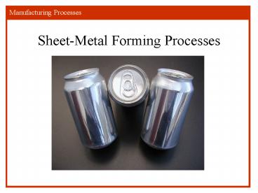
Aluminum Two-Piece Beverage Cans
- FIGURE 7.77 Aluminum two-piece beverage cans.
Note the fine surface finish. Source Courtesy of
J. E. Wang, Texas AM Univerity.
4
Metal-Forming Process for Food and Beverage
Containers
- FIGURE 7.76 The metal-forming process used to
manufacture two-piece beverage cans.
5
Punching, Blanking and Shearing Operations
- FIGURE 7.8 (a) Punching (piercing) and
blanking. (b) Examples of various shearing
operations on sheet metal.
6
Efficient Nesting of Blanks
- FIGURE 7.69 Efficient nesting of parts for
optimum material utilization in blanking. Source
Society of Manufacturing Engineers.
7
Shearing
- FIGURE 7.4 Schematic illustration of the
shearing process with a punch and die. This
process with a punch and die. This process is a
common method of producing various openings in
sheet metals.
8
Progressive Dies
- FIGURE 7.13 (a) Schematic illustration of the
making of a washer in a progressive die. (b)
Forming of the top piece of an aerosol spray can
in a progressive die. Note that the part is
attached to the strip until the last operation is
completed.
9
The Effect of Bending On Too Tight A Radius
10
Minimum Bend Radii
- TABLE 7.2 Minimum bend radii for various
materials at room temperature.
11
Common Die-Bending Operations
- FIGURE 7.22 Common die-bending operations,
showing the die-opening dimension W used in
calculating bending forces. See Eq,(7.11).
12
Presses
- Solid Gap Frame(150 tons)
- OBI
- Adjustable bed frames
- Turret Presses
13
PressBrake 30 feet, 1250 ton Niagara Machine
and Tool Works
14
Bending Operations In a Press Brake
- FIGURE 7.23 Schematic illustration of various
bending operations in a press brake.
15
Bead Forming
- FIGURE 7.25 (a) Bead forming with a single die.
(b) Bead forming with two dies in a press brake.
16
Bending
- FIGURE 7.15 (a) Bending terminology. The bend
radius is measured to the inner surface of the
bend. Note that the length of the bend is the
width of the sheet. Also note that the bend angle
and the bend radius (sharpness of the bend) are
two different variables. (b) Relationship between
the ratio of bend radius to sheet thickness and
tensile reduction of area for various materials.
Note that sheet metal with a reduction of area of
about 50 can be bent and flattened over itself
without crackling. Source After J. Datsko and C.
T. Yang.
17
Bend Allowance
- Unless specified otherwise, r t
- q positive included angle from flat
- k is a material constant
t
18
Material is 0.050 Alum. Measurements are O.D.
Holes (6) are 3/32 dia, 1/4 from edge
3.600
2.050
1.25
.550
4.570
19
Depth of Notch ________
.25
20
Bend Allowance Calculation Methods
Outside Width
Height
r usually t
r
Flat Length 2(Height-r-t) Outside Width
2(tr) 2(Bend Allowance)
21
Bend Allowance Calculation
- Determine The Bend Points
Bend Point Height-r-t1/2Bend Allowance
22
Depth of Notch Height-t-rBend Allowance Need
To Leave Room For Over Bend
Flat Length 2(Height-r-t) Outside Width
2(tr) 2(Bend Allowance)
Bend Point
Flat Length
.25
Bend Point Height-r-t1/2Bend Allowance
23
Deep-drawing Process
- FIGURE 7.50 (a) Schematic illustration of the
deep-drawing process. This procedure is the first
step in the basic process by which aluminum
beverage cans are produced today. The stripper
ring facilitates the removal of the formed cup
from the punch. (b) Variables in deep drawing of
a cylindrical cup. Only the punch force in this
illustration is a dependent variable all others
are independent variables, including the
blankholder force.
24
Explosive Forming Process
- FIGURE 7.42 Schematic illustration of the
explosive-forming process. Although explosives
are generally used for destructive purposes,
their energy can be controlled and employed in
forming large parts that would otherwise be
difficult or expensive to produce by other
methods.
25
Roll-Forming Process
- FIGURE 7.27 The roll-forming process.
- FIGURE 7.28 Stages in roll forming of a
sheet-metal door frame. In Stage 6, the rolls may
be shaped as in A or B. Source G. Oehler.
26
Fastening
- Riveting / Stitching
- Seaming /Crimping
- Welding Processes
27
Examples of Rivets and Stitching
- FIGURE 12.48 Examples of rivets (a) solid, (b)
tubular, (c) split (or bifurcated), and (d)
compression.
- FIGURE 12.49 Examples of metal stitching.
28
Designs Guidelines for Riveting
- FIGURE 12.58 Design guidelines for riveting.
Source J. G. Bralla.
29
Double-Lock Seam and Crimping
- FIGURE 12.50 Stages in forming a double-lock
seam.
- FIGURE 12.51 Two examples of mechanical joining
by crimping.
30
Home Work
- Read
- http//www.thefabricator.com/ToolandDie/ToolandDie
_Article.cfm?ID1747 - http//en.wikipedia.org/wiki/Sheet_metalCutting
- Do Sheet Metal homework located on Web CT, Print
complete turn in next lecture.

