
Using a Magnetic Angle Changing Device in a Toroidal Spectrometer PowerPoint PPT Presentation
1 / 1
Title: Using a Magnetic Angle Changing Device in a Toroidal Spectrometer
1
Using a Magnetic Angle Changing Device in a
Toroidal Spectrometer
M.R.F. Siggel-King1, D.P. Seccombe2, I. Linert3,
G.C. King4, T.J. Reddish2, M. Eypper4 and R.
Lindsay5
1) Daresbury Laboratory, Daresbury, Warrington,
WA4 4AD, U.K. 2) University of Windsor,
Department of Physics, Windsor, Ontario, N9B 3P4,
Canada3) University Gdansk Tech University, Dept
phys Elect Phenomena, PL-80952 Gdansk, Poland4)
University of Manchester, Dept Phys Astron,
Schuster Lab, Manchester M13 9PL, England5)
Institut de Ciéncia de Materials de Barcelona
(CSIC), Camput UAB, 08193 Bellaterra, Spain
Introduction A new 2D Toroidal Energy- and
Angle-Resolving Electron Spectrometer (TEARES)
has been designed and built at Daresbury
Laboratory, UK. TEARES is a multi-detection
system that analyses photoelectrons in both
energy and angle. The geometry of TEARES is
optimised for the detection of photoelectrons
ejected in the horizontal plane. This plane
generally contains the photon propagation and
polarisation vectors at SR sources and is
sometimes called the non-dipole plane. In
traditional gas-phase experiments ?-parameter
measurements are often made in the dipole plane
which is the plane orthogonal to the direction of
the photon beam. The orientation of TEARES is
particularly appropriate for the study of
non-dipole interactions such as electric
quadrupole and magnetic dipole, since the
non-dipole interactions manifest themselves most
strongly in this plane. However, both dipole and
non-dipole interactions occur in the so-called
non-dipole plan. Therefore it is essential to
accurately know the dipole (?) parameter in order
to determine the non-dipole contributions. In
many of the interesting cases the ?-parameter
must be first measured. To enable us to do this
using the TEARES spectrometer we have combined
the TEARS spectrometer with a magnetic
angle-changing device.
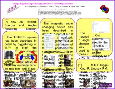
The Magnetic Angle Changer The magnetic angle
changing device has been described in detail by
Linert et al.4 It produces a localized, static
magnetic field at the interaction region of the
photoelectron spectrometer (see figure 3). This
magnetic field deflects the ejected
photoelectrons through a well-defined angle into
the stationary energy analyser of TEARES.5 The
action of the device is illustrated below in
figure 4 which shows the trajectories of
photoelectrons of different energy. Note that
although the angle of a photoelectron is changed
its point of origin, i.e. at the interaction
region, is not.The angle changer consists of two
pairs of conical coils, namely an inner pair and
an outer pair as shown. The axis of cylindrical
symmetry of the solenoids is co-linear with the
photon beam. The conical shape of the coils (see
figure 5) satisfies the geometrical condition
required to obtain an octupole moment of the
magnetic system equal to zero. The ratio of
currents in the inner and outer coils is chosen
to obtain the magnetic dipole moment of the
system also equal to zero. These properties of
the solenoid system produce a very rapid decrease
of the resultant magnetic field with radial
distance as illustrated. This ensures that the
performance of the electron analyzer is not
effected adversely. Figure 6 shows the magnetic
angle changer used in TEARES.
Results The magnetic angle changer was used to
measure He 1s photoelectrons. The measurements
were made using photons of 80 eV from the
Daresbury SRS Phoenix beamline MPW6.1. Figure
7 shows the currents used in the magnetic angle
changer as a function of deflection angle for
electrons of kinetic energy 56 eV. Figure 8
shows the normalised peak intensity as a function
of deflection angle using one side of the
toroidal analyser. The data (shown by solid blue
circles) follow a sin wave distribution. A sign
wave has been fitted to the data (pink line). The
intensities do not go to zero at ?90 degrees
because the light is not 100 linearly polarised.
Figure 7. Coil currents used for the TEARES
magnetic angle changer for electrons of kinetic
energy 56 eV.
The TEARES Spectroscopy System The TEARES
system has been described in detail by
Siggel-King et al.1-3. In brief, the TEARES
spectrometer comprises a toroidal electrostatic
deflection analyser onto which is fitted an
entrance lens, an exit lens and a two-dimensional
electron detection system (see Fig 1). The
spectrometer has been designed to accommodate
different types of experiments on various
beamlines at the Synchrotron Radiation Source
(SRS) at Daresbury and on third-generation
sources. A schematic of the electron optics of
the spectrometer is shown in Fig. 2. Electrons
are generated at the interaction region where the
light and target intersect. These electrons are
ejected in all possible radial directions those
travelling in a (horizontal) direction that is
near perpendicular to the central axis of the
spectrometer enter the double-focusing entrance
lens. Of these electrons, only those of a
selected energy will be focused onto the entrance
slit of the analyser and deflected through it.
The toroidal analyser has a cylindrical radius of
120 mm, a spherical radius of 125 mm, a sector
angle of 142.6, and an azimuthal angle of 270.
The analyser is fitted with an entrance slit and
a single-energy exit slit of 1 mm. A four-element
lens, positioned at the exit of the analyser,
focuses, demagnifyies and transports the
electrons onto the detector. The electrons are
detected using a commercially available Quantar
fast-resistive-anode imaging detector. The
spectrometer rotates about the central axis of
the spectrometer (see Fig. 2) to enable a choice
of detection angles with respect to the
propagation direction of the light. The gasseous
target was an effusive gas-jet, where the inlet
needle was mounted vertically pointing downward.
Figure 3. Magnetic angle changer principle of
operation.
Figure 4. Trajectories of photoelectrons of
differing initial energy in the magnetic angle
changer.
Figure 8. The intensity as a function of
deflection angle in the magnetic angle changer
for He 1s photoionisation using 80 eV photons.
Figure 1. The TEARES spectrometer (a)
interaction region, (b) top half of the entrance
lens, (c) bottom half of the entrance lens, (d)
toroid bridging plate shields, (e) outer toroid,
(f) exit lens assembly, (g) azimuthal edge
termination electrodes on the exit lens and at
the exit of the toroidal analyser, (h) rotation
platform, (i) vacuum chamber, and (j) guide post
(one of two) for lowering the top of the chamber
over the spectrometer.
References 1 M.R.F. Siggel-King, R. Lindsay,
F.M. Quinn, J.F. Pearson, G. Fraser, G. Thornton,
American Institute of Physics Conference
Proceedings, vol. 705, 3004, p. 937. 2 M.R.F.
Siggel-King, R. Lindsay, F.M. Quinn, J.F.
Pearson, G. Fraser, G. Thornton, J. Electron
Spectrosc. Relat. Phenom. 137-140 (2004)
721. 3 M.R.F. Siggel-King, R. Lindsay, T.J.
Reddish, D.P. Seccombe, F.M. Quinn, J. Electron
Spectrosc. Relat. Phenom., (2005) in press. 4 I
Linert , G C King and M Zubek, J. Elect. Spect.
Rel. Phenom., 134 ,(2004). 5 D Cubric, D B
Thompson, D R Cooper, G C King and F H Read.,
J.Phys.B. 30 L857 (1997).
Figure 6. The TEARES magnetic angle changer
MAC-TEARES
Figure 5. Schematic of an magnetic angle changer.
Orientations in TEARES differ.
Recommended
