
Booster Corrector Coordinate System - PowerPoint PPT Presentation
1 / 11
Title:
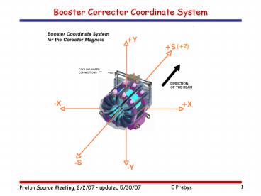
Booster Corrector Coordinate System
Description:
All corrector packages will be wired with the same polarity, ... Normal Sext. ( A3=0) _at_y=0. By=B3(x/Rref)2 ... Skew Sext. ( B3=0) _at_x=0. Bx=-A3(y/Rref)2 ... – PowerPoint PPT presentation
Number of Views:73
Avg rating:3.0/5.0
Title: Booster Corrector Coordinate System
1
Booster Corrector Coordinate System
2
General
- Requirement
- All corrector packages will be wired with the
same polarity, and this is the polarity that the
MTF will use - Conventions
- Generic convention (a la Syphers and Edwards)
- For normal elements, at y0, positive currents
give positive coefficients for - Skew elements rotated half a pole
counterclockwise from normal elements (as seen
from beam) - Determined by beam behavior
- Traditionally by effect in horizontal plane
3
Convention
- A positive current for each elements will do
the following - Follow traditional convention between normal and
skew elements - Rotate skew quadrupole 45 degrees
counterclockwise - Rotate skew sextupole 30 degrees counterclockwise
4
Dipoles (beam view)
Horizontal dipole
Vertical dipole
B
B
- Bend outward (x)
- Same as now (2006)
- Same as generic
- Bend upward (y)
- Opposite now (2006)
- Opposite generic
- Normal dipole
- ByB1
- B1 is positive
- Skew dipole
- BxA1
- A1 is negative
5
Normal Quads
By
Normal
x
- Opposite generic
- Same as now (2006)
- Positive horizontal tune change
- Negative vertical tune change
- Normal quad (A20)
- _at_y0
- ByB2x/Rref
- B2 is negative
6
Skew Quads
Skew
x
Bx
- Skew quad (B20)
- _at_y0
- BxA2x/Rref
- A2 is positive
- Opposite generic
- Same as now (2006)
- Positive horizontal tune change
- Negative vertical tune change
7
Normal Sextupole
Normal
x
By
- Normal Sext. (A30)
- _at_y0
- ByB3(x/Rref)2
- B3 is negative
- Opposite generic
- Same as now (2006)
- Positive horizontal chromaticity
- Negative vertical chromaticity
8
Sextupole
Bx
y
Skew
- Skew Sext. (B30)
- _at_x0
- Bx-A3(y/Rref)2
- A3 is positive
- Opposite generic
- Same as now (2006)
- Positive horizontal chromaticity
- Negative vertical chromaticity
9
Formalism Used By Technical Division
10
Analysis Remarks (Tech. Div.)
- Analysis registers the field angle as the
closest south pole. - Field coefficients need to be rotated into the
proper coordinate system as defined in Table 1. - Which one you grab depends on where the rotation
starts (as well as the magnet and its powering
convention). - trickier as the magnet multi-polarity gets higher
- in this case, the magnitude of the rotation is
pretty clear, the sign less so - GV used the probe simulation to arrive at the
sign (amplitude checks as well) - The rotations applied are given in Table 1.
11
Summary (Tech. Div.)
Table 1
Recommended
CrystalGraphics Presentations


