
Uniform%20Open%20Channel%20Flow - PowerPoint PPT Presentation
Title:
Uniform%20Open%20Channel%20Flow
Description:
Uniform Open Channel Flow Manning s Eqn for velocity or flow where n = Manning s roughness coefficient R = hydraulic radius = A/P S = channel slope – PowerPoint PPT presentation
Number of Views:630
Avg rating:3.0/5.0
Title: Uniform%20Open%20Channel%20Flow
1
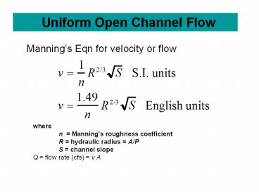
Uniform Open Channel Flow
Mannings Eqn for velocity or flow
where n Mannings roughness coefficient R
hydraulic radius A/P S channel slope Q
flow rate (cfs) v A
2
Uniform Open Channel Flow Brays B.
Brays Bayou
Concrete Channel
3
(No Transcript)
4
- Normal depth is function of flow rate, and
geometry and slope. Can solve for flow rate if
depth and geometry are known. - Critical depth is used to characterize channel
flows -- based on addressing specific energy - E y Q2/2gA2 where Q/A q/y
- Take dE/dy (1 q2/gy3) 0.
- For a rectangular channel bottom width b,
- 1. Emin 3/2Yc for critical depth y yc
- yc/2 Vc2/2g
- yc (Q2/gb2)1/3
5
In general for any channel, B top
width (Q2/g) (A3/B) at y yc Finally Fr
V/(gy)1/2 Froude No. Fr 1 for critical
flow Fr lt 1 for subcritical flow Fr gt 1 for
supercritical flow
Critical Flow in Open Channels
6
(No Transcript)
7
Optimal Channels
8
Non-uniform Flow
9
(No Transcript)
10
(No Transcript)
11
Non-Uniform Open Channel Flow
With natural or man-made channels, the shape,
size, and slope may vary along the stream length,
x. In addition, velocity and flow rate may also
vary with x.
Thus,
Where H total energy head z elevation
head, ?v2/2g velocity head
12
Replace terms for various values of S and So. Let
v q/y flow/unit width - solve for dy/dx
13
Given the Fr number, we can solve for the slope
of the water surface - dy/dx
Note that the eqn blows up when Fr 1 or So S
where S total energy slope So bed slope,
dy/dx water surface slope
14
Now apply Energy Eqn. for a reach of length L
This Eqn is the basis for the Standard Step
Method to compute water surface profiles in open
channels
15
Backwater Profiles - Compute Numerically
16
Routine Backwater Calculations
- Select Y1 (starting depth)
- Calculate A1 (cross sectional area)
- Calculate P1 (wetted perimeter)
- Calculate R1 A1/P1
- Calculate V1 Q1/A1
- Select Y2 (ending depth)
- Calculate A2
- Calculate P2
- Calculate R2 A2/P2
- Calculate V2 Q2/A2
17
Backwater Calculations (contd)
- Prepare a table of values
- Calculate Vm (V1 V2) / 2
- Calculate Rm (R1 R2) / 2
- Calculate Mannings
- Calculate L ?X from first equation
- X ??Xi for each stream reach (SEE SPREADSHEET)
18
Watershed Hydraulics
Bridge
D
QD
Tributary
Floodplain
C
QC
Main Stream
Bridge Section
B
QB
A
QA
Cross Sections
Cross Sections
19
Brays Bayou-Typical Urban System
- Bridges cause unique problems in hydraulics
- Piers, low chords, and top of road is
considered - Expansion/contraction can cause hydraulic
losses - Several cross sections are needed for a bridge
- Critical in urban settings
288 Crossing
20
The Floodplain
Top Width
21
Floodplain Determination
22
The Woodlands
- The Woodlands planners wanted to design the
community to withstand a 100-year storm. - In doing this, they would attempt to minimize any
changes to the existing, undeveloped floodplain
as development proceeded through time.
23
HEC RAS Cross Section
24
3-D Floodplain
Recommended
CrystalGraphics Presentations


