
Modeling styles: - PowerPoint PPT Presentation
Title:
Modeling styles:
Description:
Modeling styles: 1. Structural Modeling: As a set of interconnected components (to represent structure), 2. Dataflow Modeling: As a set of concurrent assignment ... – PowerPoint PPT presentation
Number of Views:53
Avg rating:3.0/5.0
Title: Modeling styles:
1
Modeling styles
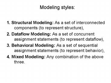
- 1. Structural Modeling As a set of
interconnected components (to represent
structure), - 2. Dataflow Modeling As a set of concurrent
assignment statements (to represent dataflow), - 3. Behavioral Modeling As a set of sequential
assignment statements (to represent behavior), - 4. Mixed Modeling Any combination of the above
three.
2
Structural Style of Modeling
- In the structural style of modeling, an entity is
described as a set of interconnected components. - entity HALF_ADDER is
- port (A, B in BIT SUM, CARRY out BIT)
- end HALF_ADDER
- -- This is a comment line.
3
model for the HALF_ADDER entity
- architecture HA_STRUCTURE of HALF_ADDER is
- component XOR2
- port (X, Y in BIT Z out BIT)
- end component
- component AND2
- port (L, M in BIT N out BIT)
- end component
- begin
- X1 XOR2 port map (A, B, SUM)
- A1 AND2 port map (A, B, CARRY)
- end HA_STRUCTURE
4
Dataflow Style of Modeling
- The dataflow model for the HALF_ADDER is
described using two concurrent signal assignment
statements - architecture HA_CONCURRENTof HALF_ADDER is
- begin
- SUM lt A xor B after 8 ns
- CARRY lt A and B after 4 ns
- end HA_CONCURRENT
- Concurrent signal assignment statements are
concurrent statements, and therefore, the
ordering of these statements in an architecture
body is not important.
5
Behavioral Style of Modeling
- The behavioral style of modeling specifies the
behavior of an entity as a set of statements that
are executed sequentially in the specified order. - This set of sequential statements, that are
specified inside a process statement, do not
explicitly specify the structure of the entity
but merely specifies its functionality. - A process statement is a concurrent statement
that can appear within an architecture
6
For example, consider the following behavioral
model for the DECODER2x4 entity.
- architecture DEC_SEQUENTIAL of DECODER2x4 is
- begin process (A, B, ENABLE)
- variable ABAR, BBAR BIT
- begin
- ABAR not A -- statement 1
- BBAR not B --statement 2
- if (ENABLE '1') then statements
- Z(3) lt not (A and B) - statement 4
- Z(0) lt not (ABAR and BBAR) statement 5
- Z(2) lt not (A and BBAR) - statement 6
- Z(1 ) lt not (ABAR and B) - statement 7
- else
- Zlt "1111" -statements
- end if
- end process
- end
7
- A process statement, too, has a declarative part
(between the keywords process and begin), and a
statement part (between the keywords begin and
end process). - The statements appearing within the statement
part are sequential statements and are executed
sequentially. - The list of signals specified within the
parenthesis after the keyword process constitutes
a sensitivity list and the process statement is
invoked whenever there is an event on any signal
in this list. - In the previous example, when an event occurs on
signals A, B, or ENABLE, the statements appearing
within the process statement are executed
sequentially.
8
Mixed Style of Modeling
- It is possible to mix the three modeling styles
that we have seen so far in a single architecture
body. - That is, within an architecture body, we could
use component instantiation statements (that
represent structure), concurrent signal
assignment statements (that represent dataflow),
and process statements (that represent behavior).
9
Example of a mixed style model for a one-bit
full-adder
- entity FULL_ADDER is
- port (A, B, CIN in BIT SUM, COUT out BIT)
- end FULL_ADDER
- architecture FA_MIXED of FULL_ADDER is
- component XOR2
- port (A, B in BIT Z out BIT)
- end component
- signal S1 BIT
- begin
- X1 XOR2 port map (A, B, S1 ) --
structure. - process (A, B, CIN)
-- behavior. - variable T1, T2, T3 BIT
- begin
- T1 A and B
- T2 B and CIN
- T3A and CIN
- COUT lt T1 or T2 or T3
- end process
Recommended
CrystalGraphics Presentations


