
I/O Example: Disk Drives - PowerPoint PPT Presentation
Title:
I/O Example: Disk Drives
Description:
I/O hardware must contains some logical circuit to communicate with CPU ... Allow processors, memory, and I/O devices to coexist ... – PowerPoint PPT presentation
Number of Views:24
Avg rating:3.0/5.0
Title: I/O Example: Disk Drives
1
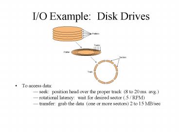
I/O Example Disk Drives
- To access data seek position head over the
proper track (8 to 20 ms. avg.) rotational
latency wait for desired sector (.5 / RPM)
transfer grab the data (one or more sectors) 2
to 15 MB/sec
2
How CPU talk to IO device?
- I/O hardware must contains some logical circuit
to communicate with CPU - Typically I/O hardware have some internal memory,
called I/O registers - Those I/O registers can be accessed though some
addresses burned into the device in prior. - CPU can read/write those addresses
- CPU treat them as memory addresses
- I/O registers can be
- Control register when CPU write a particular
value to this address, a particular I/O function
will be done - Status register CPU can read this address to see
the current status of the device. - Data register contain data CPU want from the I/O
device.
3
A typical I/O procedure to read one byte from a
I/O device
- CPU send a command to the control register of a
I/O device - CPU keep reading the status register until data
is ready. - CPU read the data register
4
How CPU Interact with I/O Dev
- For a read,
- CPU supplies address and transaction type (read)
- Yes, each I/O device has an address, like memory
slots. - Device places data on data bus and indicates data
ready (how?).
- Read serial port (RS-232)
- outport(0x2fb, 1)
- While (1)
- status inport (0x2fc)
- if (status1)
- y inport (0x2fd)
- break
5
Main mem
- Memory-Mapped I/O
- Device is controlled by writing certain commands
to the device controllers register - The address for Device controllers register
overlapped with main memory - MIPS I/O is done through lw and sw instruction.
- X86 The I/O instructions IN and OUT move data
between I/O ports and CPU register - Some CPUs only execute IO instructions in
"supervisor mode".
IO Dev 1
Internal register
IO Dev 2
Internal register
6
What is BUS
- A bus is a shared communication link
- Including data, address and control
- A bus transaction includes two parts
- Sending the address and requested action
- Receiving or sending the data (blocks)
7
Bus Adapter
- The I/O code showed early is not efficient
- User bus adapter to relieve CPU from low IO
operations. - Usually a simple chip that execute desired bus
transaction - Many bus adapter are connected to a common
physical bus - the one start bus trans is called the bus master
- The one response to the bus req is called the bus
slave - Most IO controllers, your desktop motherboard
contains many such chips, can act as both master
and slave - A bus transaction still must be kicked off by
your program - Typically several IO instructions
8
Type of IO Bus
- Processor-Memory Bus, Connects directly to the
processor - Short and high speed
- Only need to match the memory system
- I/O Bus
- Usually is lengthy and slower,
- Need to match a wide range of I/O devices
- Connects to the processor-memory bus
- many subtypes ISA, PCI, USB..
- Differ in the number of data lines
- Backplane Bus
- Allow processors, memory, and I/O devices to
coexist - Arbitration Support multiple device of same bus
protocols - E.g., if the system has two network interface
cards, how to determine which one can use the
shared bus?
9
Typical Desktop Bus
10
Support Efficient IO
pollingalways work, IO controller is the most
simply interrupts IO controller must be able to
raise a line when data is ready DMA Can
initiate a bus transaction to transfer data
between the device and other components (MEM or
other IO device)
11
INTERRUPT I/O
- Steps involved in interrupt I/O
- The external device, when ready and needs CPU
service gives an interrupt request signal to the
CPU. - The CPU completes the current instruction cycle
and sends an interrupt acknowledgement signal
back to the I/O device. - The device provides an interrupt vector number to
the CPU so that the processor generates the
starting address of the ISR. - The CPU saves PC, status register, and data
registers on the stack and loads PC with the
starting address of the ISR. - The CPU completes the execution of the ISR,
restores register values, and returns back to the
main program
12
DMA I/O
- Steps involved in DMA
- The I/O device gives a DMA request to the CPU
through the DMA controller. - The CPU completes the current microinstruction
cycle. - The CPU loads the DMA controller with the
starting address of the block of data that needs
to be transferred, the size of the block, and the
address of the device that has requested the
transfer. - The CPU then isolates from the system and sends a
DMA acknowledge signal back to the DMA controller
to let it know that the DMA controller can take
control over the system buses.
13
Example what happens when you fwrite(fd, buf,
4096k)
- Your code call the driver and move on
- the disk driver (upon interrupt)
- Calculate the phy disk block
- Write disk block to IDE controller
- Write buf addr to the IDE controller
- Write a start command to IDE controller
- IDE controller
- read one block from memory and write to disk
(DMA) - When done, raise interrupt and trigger the disk
driver
Recommended
CrystalGraphics Presentations


