
Feedback%20Control%20of%20Flexible%20Robotic%20Arms - PowerPoint PPT Presentation
Title:
Feedback%20Control%20of%20Flexible%20Robotic%20Arms
Description:
Design Challenges. Modeling of Flexible Robotic Arms. State Observer Simulation ... Source: http://archives.cnn.com/2000/TECH/space/08/21/canada.hand/index.html ... – PowerPoint PPT presentation
Number of Views:82
Avg rating:3.0/5.0
Title: Feedback%20Control%20of%20Flexible%20Robotic%20Arms
1
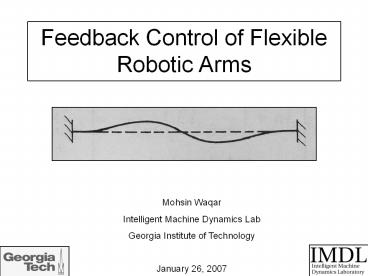
Feedback Control of Flexible Robotic Arms
Mohsin Waqar Intelligent Machine Dynamics
Lab Georgia Institute of Technology January 26,
2007
2
My Background in Brief
Education BS Degree in Mechanical
Engineering, Cum Laude, May 2006
San Jose State University, San Jose,
California Senior Design Project
Injection Molding Machine Tending Robot
Work Experience Automation Intern RAININ
INSTRUMENT LLC, Oakland, CA, June 2005 July
2006 Truck Assembly Maintenance Co-op NEW
UNITED MOTOR MANUFACTURING INC, Fremont, CA,
January August 2004
3
Presentation Overview
- Project Goals and Motivation
- What is a Flexible Robotic Arm?
- Design Challenges
- Modeling of Flexible Robotic Arms
- State Observer Simulation in MATLAB
- Tentative Experimental Setup
- Project Roadmap
4
Problem Statement
- Expand field of active vibration suppression
(Ryan Krauss, Spring 2006) - Implement novel control approaches (Ryan Krauss,
Spring 2006)
- What suitable sensors can be used to receive
vibration feedback from a single link flexible
robotic arm? - What suitable observer can be used to estimate
the position of the end point of a flexible
robotic arm, based on corrupted measurements? - What suitable control scheme can be used to make
this closed-loop system robust to parameter
uncertainty?
5
Motivation for Research
1) Manipulators with very large workspaces (long
reach) Example - handling of nuclear waste. 2)
Manipulators with constraints on mass Example
space manipulators. 3) Manipulators with
improved performance Examples - truly high
precision, quicker motion, less energy
requirement, and lower cost.
Source http//archives.cnn.com/2000/TECH/space/08
/21/canada.hand/index.html
6
What is a Flexible Robotic Arm?
Source Shabana, A. A. Vibration of Discrete and
Continuous Systems. 1997.
- Robotic arm is subject to torsion, axial
compression, bending. - Structural stiffness, natural damping, natural
frequencies and boundary conditions are important
to understand. - Its NOT that we want to design flexible robotic
arms, but we do have to deal with them. - Design focus Accuracy, repeatability and
steadiness of the beam end point.
7
Design Challenges
- Accurate Modeling of Flexible Structure and
Actuator - System Nonlinearities
- Non-minimum Phase Behavior
- Parameter Uncertainty
- Corrupted Sensor Measurements
8
Non-Minimum Phase Behavior
- Causes
- 1) positioning of sensors (non-collocation) and
2) flexible nature of robot links - Detection
- System transfer function has zeros
- in right half plane.
- Poles and zeros in S-plane are not interlaced.
- Effects
- Limited speed of response.
- End point of flexible arm initially moves in
wrong direction. - Unstable in closed loop with increasing
controller gain. - Parameter variation becomes more troubling
(Zero-flipping).
Source Cannon, R.H. and Schmitz, E. Initial
Experiments on the End-Point Control of a
Flexible One-Link Robot. 1984.
Im
X
X
X
Re
Accurate knowledge of natural frequencies and
damping ratios becomes a requirement.
9
Flexible Arm Modeling
- Lumped Mass System (or Discrete System)
- For approximating a distributed parameter system.
- Results in multi-degree of freedom system.
- Finite degrees of freedom.
- Described by one second-order ODE per
degree/order of the system. - Distributed Parameter System (or Continuous
System) - Symbolic form retains infinite degrees of freedom
and non-minimum phase characteristics. - Describes rigid body motion of link and elastic
deflection of link. - Described by second order PDE.
- Several Approaches
- Lagrangian Obergfell (1999)
- Newton Euler Girvin (1992)
- Approximate methods
- Transfer Matrix Method Krauss (2006), Girvin
(1992)
Mashner (2002) Beargie (2002)
10
Simple Model of Single Link
M2
k
F
M1
- Recall Project Goal
- What suitable observer can be used to estimate
the position of the end point of a flexible
robotic arm, based on corrupted measurements?
11
Overview of Kalman Filter
- Why Use?
- Needed when internal states are not measurable
directly (or costly). - Needed in presence of noise process noise
- input noise
- Notable Aspects
- Recursive Nature
- Optimal chooses estimate which minimizes sum of
squares of error (like least squares estimation).
- Predictor-Corrector Nature
12
Overview of Kalman Filter
Noise Covariance Matrices Q and R measure of
uncertainty in plant and in measurements,
respectively. Higher values for a matrix element
means lots of uncertainty in a process state or
in a measurement. Error Covariance Matrix P -
measure of uncertainty in state estimates. Higher
elements mean high uncertainty in pre-measurement
estimate so weight measurements heavier. Depends
on process noise. Kalman Matrix K -
determines how much to weight fresh estimates
based on a recent measurement (correcting
estimate). Depends on Error Covariance Matrix P.
How it works Step 1. Declare Initial Conditions
Error Covariance Matrix P, initial state guess
x. Step 2. Declare Filter Parameters Noise
Covariance Matrices Q and R. Step 3. Predict
States x based on Plant Dynamics Step 4. Update
Error Covariance Matrix P (increase) Step 5.
Update Kalman Matrix K Step 6. Correct State
Estimate x based on measurement Step 7. Update
Error Covariance Matrix P (decrease) Iterate
through Steps 3 7 .
At Steady State P, K become constant. If Q, R
and system matrices A, B, C already constant can
use steady state Kalman filter.
13
Steady State Kalman Filter Simulation
14
Steady State Kalman Filter Simulation
R 0.1
R 1
R 0.01
15
Tentative Experimental Setup
Commanded Tip Position
Linear Servomotor
Controller
Flexible Arm
-
Other State Estimates
Sensors
Estimate for Tip Position
Estimator
This has been done before by Beargie and Mashner
in 2002!
16
Roadmap
- Phase I. Analysis and Simulation
- System Modeling
- Simulate Noisy Conditions
- Observer Design
- Controller Design
- Phase II. Experimental
- Familiarize with testbed customize
- Sensor Experiments
- Observer Design
- Controller Design
17
Roadmap
- Phase I. Analysis and Simulation
- System Modeling
- Simulate Noisy Conditions
- Observer Design
- Controller Design
- Phase II. Experimental
- Familiarize with testbed customize
- Sensor Experiments
- Observer Design
- Controller Design
Questions?
Recommended
CrystalGraphics Presentations


