
ca. Mar 2, 2004 - PowerPoint PPT Presentation
Title:
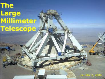
ca. Mar 2, 2004
Description:
2001: Factory Steel Fabrication and Trial Assembly. 2002-2004: Installation of Steel at Site ... 2004-2006: Fabrication of Surface Panels. 2005-2006: ... – PowerPoint PPT presentation
Number of Views:57
Avg rating:3.0/5.0
Title: ca. Mar 2, 2004
1
TheLargeMillimeterTelescope
ca. Mar 2, 2004
2
Gopal Narayanan, Min Yun, F. Peter
Schloerb University of Massachusetts Luis
Carrasco Instituto Nacional de Astrofisica,
Optica, y Electronica presented on behalf of the
INAOE-UMass LMT Collaboration
3
Sierra NegraThe LMT Site
Pico de Orizaba
Sierra Negra
- state of Puebla, MX
- excellent mm-wave transmission
- 4600m elevation
- 19 degrees Latitude
- Benign conditions
- Development nearly complete
4
LMT Specifications
5
LMT Time Line
- 1997 Site Selection
- 1997-2000 Antenna Design
- 1999-2002 Site Preparation and installation of
Foundation - 2001 Factory Steel Fabrication and Trial
Assembly - 2002-2004 Installation of Steel at Site
- 2004-2006 Fabrication of Surface Panels
- 2005-2006 Installation of Surface Panels
- 2005 Commissioning Begins
6
Backstructure
Surface Segments
Elevation Wheels
LMT Design
Receiver Cabin
Alidade
Foundation
7
Construction at Site
January 2001
January 2002
February 2002
April 2003
May 2002
July 2002
8
Present Status at SiteApril 2004
9
Initial LMT Instruments
- Spectral Line
- SEQUOIA 32 element array for 3mm band
- Array Autocorrelation Spectrometers
- Redshift Receiver 3mm ultrawide band receiver
- 1mm SIS Receiver
- Continuum
- BOLOCAM II 144 element focal plane array
- SPEED special array for spectral energy
distribution measurements
10
Goldsmith, Narayanan, Heyer, Snell Brunt (2004)
11
Redshift Search Receiver
- Ultra-wideband receiver for astronomical search
for the highly redshifted spectral lines from
distant galaxies. - 75-111 GHz gives high probability of detecting
one line from galaxies with redshift greater than
1.1 and 2 lines for Z gt 3
2mm, 5mm PWV, TRCR 60K
12
- Dual polarization two beams
- Backend spectrometer is analog autocorrelator
with 6.5 GHz bandwidth per section. 30 MHz
resolution.
13
LMT Redshift Measurements
Simulations based on dusty QSO BR 1335-0417.
ULIRG Line Ratios
LMT has sensitivity to conduct follow-up studies
on objects discovered in continuum surveys.
14
1mm SIS Commissioning Receiver for LMT (testbed
for future focal-plane array)
15
First Generation Continuum Receivers for LMT
- BOLOCAM II
- Imaging continuum receiver
- copy of the BOLOCAM instrument
- (Caltech, JPL, Cardiff, Colorado)
- 144 element focal plane array
- key technology for
- Herschel/SPIRE
- BLAST
BOLOCAM detector array
16
LMT Continuum Studies of Distant Objects
Simulation of 1 hour LMT observation with
Bolocam II at 1.1 mm 9.5x9.5 arcmin (0.02 sq.
deg.) 0.5 mJy rms
LMT will discover many 1000's of protogalaxies
with continuum maps.
Simulation by Chapin, Hughes and Gaztenaga -
INAOE
17
First Generation Continuum Receivers for LMT
- SPEED
- designed to measure mm-wave SED of previously
detected objects - simultaneous multi-frequency measurements
- matched beams in all bands
- high per-pixel sensitivity
- takes advantage of new bolometer technologies
- TES detectors
- Frequency Selective Bolometers
Ch.4
Ch.3
Ch.2
Ch.1
FSB Detector
FSB Backshort
18
Protogalaxy Interrogation with SPEED
SED of CFRS14A
SPEED 5s sensitivities after 4 minutes of
integration at LMT.
19
Comparison of LMT to Other Telescopes
20
Performance Comparison With Respect to the LMT
21
- Analog Autocorrelator
- Like digital autocorrelator but delays and
multiplies done with analog circuitry. No input
digitizer, so no loss of S/N. Much wider
bandwidth practical. - Analog delay lines Nyquist sampled for 8 GHz
bandwidth. Only 1.5-8 GHz used. - 64 lags on each tapped line, 4 lines per board.
256 lags total giving 31 MHz resolution, all on a
single circuit board. - Taps are summed and multiplied with silicon
diodes. - Circuit board includes A/D converters and digital
signal processing. - 24 boards cover full receiver bandwidth of 144
GHz. - Total materials cost about 10/resolution element.
22
LMT Sensitivity to Distant Dusty Starburst
Galaxies
23
OperationsThe Large Millimeter Telescope
Observatory
- LMTO Role
- Telescope maintenance and operation
- Development of plans for upgrades
- Telescope user support
- Outreach
- LMTO Organization
- Governing Board composed of INAOE and UMass
personnel oversees LMTO. - LMTO is separate entity with an indepentent
Director and Staff.
24
LMTO A Scientific Collaboration between the US
and Mexico
25
LMT Site MM-wave Transmission
2mm ppt-H2O
8mm H2O
8mm ppt-H2O
2mm H2O
Site Opacity Quartiles based on
Radiometric Measurements
Predicted Transmission for 2mm and 8mm ppt water
vapor
26
Antenna Design
- Antenna Designer MAN Technologie
- "Open Air" Design (no enclosure).
- Active Surface
- 180 trapezoidal surface segments.
- Actuators at four corners of segments.
- open-loop lookup table for positioning.
- Use of Active Surface eliminates gravitational
distortion as major error source.
27
Antenna Fabrication
- Steel Fabrication
- Adriann's de Mexico, Tlanepantla, Mexico
- Supervision by Antedo, Inc., Cupertino CA.
- Steel Fabrication is complete antenna being
assembled at site - Surface Panels
- Design and Development by Composite Optics Inc.
(COI), San Diego, CA - Fabrication at Adriann's de Mexico
- Panel fabrication to begin this year.
28
LMT Surface Segment
Surface Panel
Actuator for Computer Control
Subframe
29
Critical Design Review for First Panel
Composite Optics Inc. San Diego CA
30
(No Transcript)
Recommended
CrystalGraphics Presentations


