
Design of a Multi-Stage Compressor - PowerPoint PPT Presentation
1 / 63
Title:
Design of a Multi-Stage Compressor
Description:
Design of a Multi-Stage Compressor Motivation: ... Preliminary studies will show that a single-spool all-axial flow machine is OK, ... – PowerPoint PPT presentation
Number of Views:607
Avg rating:3.0/5.0
Title: Design of a Multi-Stage Compressor
1
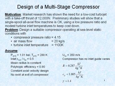
Design of a Multi-Stage Compressor
- Motivation Market research has shown the need
for a low-cost turbojet with a take-off thrust of
12,000N. Preliminary studies will show that a
single-spool all-axial flow machine is OK, using
a low pressure ratio and modest turbine inlet
temperatures to keep cost down. - Problem Design a suitable compressor operating
at sea-level static conditions with - compressor pressure ratio 4.15
- air mass flow 20 kg/s
- turbine inlet temperature 1100K
- Assume
- Pamb 1.01 bar, Tamb 288 K Utip 350 m/s
- Inlet rhub / rtip 0.5 Compressor has no
inlet guide vanes - Mean radius is constant
- Polytropic efficiency 0.90
- Constant axial velocity design
- No swirl at exit of compressor
2
Steps in the Meanline Design Process
- Steps
- 1) Choice of rotational speed and annulus
dimensions - 2) Determine number of stages, using assumed
efficiency - 3) Calculate air angles for each stage at the
mean radius - meanline analysis - 4) Determine variation of the air angles from
root to tip - radial equilibrium - 5) Investigate compressibility effects
- 6) Select compressor blading, using
experimentally obtained cascade data or CFD - 7) Check on efficiency previously assumed
- 8) Estimate off-design performance
3
Compressor Meanline Design Process
- Steps
- Choose Cx1 and rH/rT to satisfy m and keep Mtip
low and define rT - Select N from rT and UT
- Compute ?T0 across compressor and all exit flow
conditions keep rm same through engine - Estimate ?T0 for first stage from inlet condtions
Euler and de Haller - Select number of stages ? ?T0comp / ?T0stage
- ..
- ..
4
Step 1- Choice of Rotational Speed Annulus
Dimensions
- Construct table of inlet / exit properties and
parametric study of c1x vs. tip Mach number next
chart - Chose c1x from spread sheet to avoid high tip
Mach numbers and stresses - Calculate ?1 from inlet static pressure and
temperature - With mass flow 20 kg/s and rhub/rtip 0.5
- and compute rotational speed and tip Mach number
5
Calculate Tip Radius and Rotational Speed
Drive choice by compressor inlet conditions
6
Compute Root (Hub) and Mean Radius
- Choose N 250 rev/sec or 15,000 RPM and
rhub/rtip 0.5 - With hub/tip radius ratio and tip radius
7
Compressor Meanline Design
- Given m, Utip, p01, T01, Pr, ?poly and c1x
chosen to avoid high tip Mach numbers and
stresses - Compressor inlet (1)
Select RH/RT and Utip (N) for turbine issues
8
Compressor Meanline Design
- Compressor exit (2)
9
Compute Compressor Exit Conditions
- Compute Compressor Exit Total Temperature
- so that T02 288.0 (4.15)0.3175 452.5 0K,
- DT0 compressor 452.5 - 288.0 164.5 0K and
other conditions
10
Compute Compressor Exit Conditions
- Exit area, hub and tip radius
11
Step 2 - Estimate the Number of Stages
- From Eulers Turbine Equation
- With no inlet guide vane (Cu10, a1 0, and Wu1
-U), the relative flow angle is - And the relative inlet velocity to the 1st rotor
is
12
Maximum Diffusion Across Compressor Blade-Row
- There are various max. diffusion criteria. Every
engine company has its own rules. Liebleins
rule is one example. Another such rule is the de
Haller criterion that states - This criteria can also take the form of max.
pressure ratio with correlations for relative
total pressure loss across the blade row as a
function of Mach number, incidence,
thickness/chord, etc. Taking the maximum
diffusion (de Haller), leads to
Note that de Hallers criterion is simpler than
Liebleins rule since it does not involve
relative circumferential velocities or solidity.
To first order, this is same as a 0ltDfactorlt0.4.
Could use Liebleins rule but would have to
iterate.
13
Choose Number of Stages
- Given ?poly and T0out/T0in ? ?T0 T0out
-T0in, so the number of stages is DT0 compressor
/ DT0stage 164.5/28 5.9 - Typically (?T0)stage ? 40K (subsonic) - 100K
(transonic) - Therefore we choose to use six or seven stages.
To be conservative (account for losses, ie.
halt1), - Choose 7 stages
- Recalculate the DT0stage 164.5/7 23.5
- So 1st stage temperature ratio is T0 ratio 288
23.5/288 1.0816 - The stage pressure ratio is then P0 ratio (T0
ratio ) hpg / (g - 1) 1.2803
14
Compressor Meanline Design
- Develop estimate of the number of stages
- Assuming Cx constant
- for axial inflow tan?1 Um/Cx
- V1 Cx / cos ?1
- de Haller criterion (like Dfactor) V2/V1 ? 0.72
- cos ?2 Cx/V2
- neglect work done factor (?1) ? (?T0)stage
. - (?T0)stage Nstages ? T0out -T0in
- Select Nstages and select nearly constant set of
(?T0)stage - Develop Stage by Stage Design
- Assume that continual blockage buildup due to
boundary layers reduces work done, therefore
15
Compressor Meanline Design
- Develop Stage by Stage Design
- C absolute velocity, CU absolute
velocity in U direction
W2
C2
Constant Cx
C1
W1
U
16
Step 3 - Calculate Velocity Triangles of 1st
Stage at Mean Radius
- So from Euler Turbine Equation
- We can re-calculate the relative angles for the
1st stage
17
Velocity Components and Reaction of 1st Stage
- The velocity components for the 1st stage (rotor)
are therefore - The Reaction of the 1st stage is given by
18
Velocity Components for Stator of 1st Stage
- Now consider the stator of the 1st stage. The
Dh0 of the stator is zero so from Eulers eqn. - If design uses assumption of repeating stage,
then inlet angle to stator is absolute air angle
coming out of rotor and, exit absolute angle of
stator is inlet absolute angle of rotor
19
Velocity Triangles of 1st Stage Using Repeating
Stage Assumption
Notice that the velocity triangles are not
symmetric between the rotor and stator due to
the high reaction design of the rotor. The rotor
is doing most of the static pressure
(temperature) rise.
Cx1150
a10
W C - U
b160.64
U- WU1 266.6
W1305.9
Cx3150
STATOR
a30
b360.64
C2174.21
a230.57
U266.6
CU288.6
W3305.9
Cx2150
ROTOR
U266.6
b249.89
WU2178.0
W2232.77
20
Stage Design Repeats for Stages 2-7
- Then the mean radius velocity triangles
essentially stay the same for stages 2-7,
provided - mean radius stays constant
- hub/tip radius ratio and annulus area at the exit
of each stage varies to account for
compressibility (density variation) - stage temperature rise stays constant
- reaction stays constant
- If, however, we deviate from the repeating
stage assumption, we have more flexibility in
controlling each stage reaction and temperature
rise.
21
Non- Repeating Stage Design Strategy
- Instead of taking a constant temperature rise
- across each stage, we could reduce stage
temperature rise for first and last stages of the
compressor and increase it for the middle stages.
This strategy is typically used to - reduce loading of first stage to allow for a wide
variation in angle of attack due to various
aircraft flight conditions - reduce turning required in last stage to provide
for zero swirl flow going into combustor - With this in mind, lets change the work
distribution in the compressor to
22
1st Stage Design for Non-Repeating Stages
- We can re-calculate the relative angles for the
1st stage
23
Velocity Components and Reaction of 1st Stage
with Non-Repeating Stages
- The new velocity components for the 1st stage
(rotor) are therefore - The Reaction of the 1st stage is given by
24
Design of 1st Stage Stator
- The pressure ratio for this design with a
temperature change, DT0 20 is - So P03 P02 1.01 (1.236) 1.248 bar and T03
28820308 0K - Now we must choose a value of a3 leaving the
stator. - When we designed with repeating stages, a3 a1.
- But now we have the flexibility to change a3.
25
Design of the 1st Stage Stator the 2nd Stage
- Change a3 so that there is swirl going into the
second stage and thereby reduce the reaction of
our second stage design. - Design the second stage to have a reaction of
0.7, then from the equation for reaction - And if we design the second stage to a
temperature rise of 25 0, the Eulers equation - Which can be solved simultaneously for b1and b2
26
Design of 1st Stage Stator 2nd Stage Rotor
- Note that this is same as specifying E, n, and R
as in one of your homeworks and computing the
angles. - And absolute flow angles of second stage can be
found from - So
- Therefore, we have determined the velocity
triangles of the 1st stage stator and the second
stage rotor
27
Velocity Triangles of 1st Rotor Using
Non-Repeating Stage Assumption
Cx1150
Notice that the velocity triangles are not
symmetric due to the high reaction design of
the rotor. Also, there is swirl now leaving the
stator.
a10
W C - U
b160.64
U- WU1 266.6
C3153.56
W1305.9
STATOR
a312.36
Cx3150
CU332.87
b357.31
C2167.87
U266.6
a226.68
CU275.38
W3277.73
Cx2150
U266.6
ROTOR
b251.89
WU3233.77
WU2191.22
W2242.03
28
Design of 2nd Stage Stator 3rd Stage Rotor
- Design of 2nd stage stator and 3rd stage rotor
can be done in same manner as 1st stage stator
and 2nd stage rotor. - A choice of 50 reaction and a temperature rise
of 25 degrees for 3rd stage will lead to
increased work by stage but a more evenly
balanced rotor/stator design. The velocity
triangle of the stator will be a mirror of the
rotor. - This stage design will then be repeated for
stages 4 - 6.
29
Class 12 - The 7-Stage Compressor Design So Far
Has Lead to 1st and 2nd Stages
30
Design of 2nd Stage Stator
- The pressure ratio for the 2nd stage design with
a temperature change, DT0 25 is - So P03 P02 1.248 (1.279) 1.596 bar and T03
30825333 0K - Now we must choose a value of a3 leaving 2nd
stage stator that provides for the desired
Reaction and Work in 3rd stage using a similar
technique as previously used.
31
Design of 2nd Stage Stator 3rd Stage
- We can change a3 so that there is swirl going
into third stage and thereby reduce reaction of
second stage design. If we design third stage to
have a reaction of 0.5, then from equation for
reaction - And if we design third stage to a temperature
rise of 25 0, Eulers equation - Which can be solved simultaneously for b1and b2
32
Design of 2nd Stage Stator 3rd Stage Rotor
- And the absolute flow angles of the second stage
can be found from - So
- Note the symmetry in angles for 3rd stage due to
the 50 reaction ! - Therefore, we have determined the velocity
triangles of the 2nd stage stator and the third
stage rotor. Check the de Haller number for the
3rd stage rotor
33
Velocity Triangles of 2nd Stage
C3153.56
W C - U
a312.36
Cx3150
CU332.87
b357.31
C3172.99
U266.6
a329.88
Cx3150
CU386.18
W3277.73
STATOR
b350.26
U266.6
WU3233.77
C2196.59
W3234.63
a240.27
CU2127.07
Cx2150
ROTOR
WU3180.42
U266.6
b242.92
WU2139.53
W2204.86
Notice that the velocity triangles are not
symmetric for the second stage due to
70reaction design but will be for 3rd stage (50
reaction).
34
Summary of Conditions for Stages 1 - 3
35
Design of Stages 4-6
- The velocity triangles of stages 4 through 6 will
essentially be repeats of stage 3 since all have
a 50 reaction and a temperature rise of 25
degrees. - Stagnation and static pressure as well as
stagnation and static temperature of these stages
will increase as you go back through the machine.
- As a result, density will also change and will
have to be compensated for by changing the
spanwise radius difference (area) between the hub
and tip (i.e. hub/tip radius ratio)
36
Velocity Triangles of Stages 3 - 6
C3172.99
W C - U
a329.88
C3172.99
Cx3150
CU386.18
b350.26
a329.88
Cx3150
CU386.18
STATOR
U266.6
b350.26
U266.6
W3234.63
W3234.63
WU3180.42
C2234.63
CU2180.42
WU3180.42
a250.26
Cx2150
ROTOR
U266.6
b229.88
WU286.18
W2172.99
Notice that the velocity triangles are
symmetric due to the 50reaction design.
37
Summary of Conditions for Stages 1 - 6
38
Stage 7 Design
- So going into stage 7, we have P01 3.65 and T01
433. The requirements for our 7-stage
compressor design we have - P0 exit 4.15 1.01 4.19 bar
- T0 exit 288.0 (4.15)0.3175 452.5 0K
- This makes the requirements for stage 7
39
Stage 7 Design
- If we assume a Reaction 0.5 for the 7th stage
- Then, solving equations
40
Stage 7 Design
- And from
- or from symmetry of the velocity triangles for
50 reaction - Note that the absolute angles going into stage 7
have changed from those computed for stages 3 - 6
and that the exit absolute air angle leaving the
compressor is 32.770. This means that a
combustor pre-diffuser is required to take all of
the swirl out of the flow prior to entering the
combustor.
41
Summary of Compressor Design
42
Hub and Tip Radii for Each Blade Row
- From the pressure and temperature, we can compute
the density from the equation of state
43
Hub and Tip Radii for Each Blade Row
- From Continuity
- and our design value of rmean 0.1697,
- we can calculate the hub and tip radii (i.e.
area) at the entrance and exit of each blade row
44
Hub Tip Radii for All Stages of Compressor
- So we get
rotor stator rotor stator rotor stator rotor stato
r rotor stator rotor stator rotor stator
45
Conditions in Compressor
46
Hub Tip Radii Distribution - Flow Path Area
47
Spanwise Variations
- Blade wheel speeds vary with radius leading to a
change in velocity triangles with span for each
blade row. For instance, the first blade row has
- rhub .1131, rmean .1697, rtip
.2262 m and - Uhub 177.7 , Umean 266.6, Utip 355.3
m/s - leading to relative flow angles
- Next, we must choose the type of radial design
strategy from - free vortex where CU r constant (dh0/dr 0)
- constant reaction where U DCU constant
- exponential where CU1 a - (b/R) and CU2 a
(b/R) - The exit radial pressure gradient will be
different for each of the designs
48
Real World Effects
- 3-Dimensional effects
- radial equilibrium
- free vortex designs
- secondary flows
- Tip speed limitations ? maximum blade stresses
(later) - Axial velocity ? compressibility, shocks, losses
- High flow deflection ? Dfactor, de Haller,
Carters rule - Blockage (Kbar) due to boundary layers ? work
done factor ?
49
Axisymmetric Flow Analyses
- Consider axisymmetric flows and
steady flow - In the radial direction,
50
Radial Equilibrium
If Cr0 and Pressure Balances Centrifugal Forces,
and streamline curvature effects neglected then
51
Simple Radial Equilibrium
- So from the radial momentum equation
- reduces to
- Tds/dr represents the spanwise variation in
relative loss. If this is assumed to be zero,
then (Simple Radial Equilibrium Equation with
Cr0)
52
Simple Radial Equilibrium
- Now
- So that we get (vortex energy equation)
- If dh0/dr 0 (work is constant with r) and we
assume that CXconstant as a function of span,
then
53
Simple Radial Equilibrium
- One important variations / solutions to this
equation - Free vortex flow
- Later we will see more general form of this
equaion will lead to another solution for forced
vortex flow
54
Consider Free Vortex Design for 1st Stage Rotor
- CU r constant so that
- So that at the exit of the first stage rotor we
have
55
Free Vortex Design for 1st Stage Rotor
- The axial velocity Cx is assumed to be constant
as a function of radius (Note that it doesnt
have to be !)
56
1st Stage Blade Spanwise Variations (Free Vortex
Design)
W C - U
Cx1150
a10
W1h232.5
b1h49.83
Uh- WU1h 177.7
C2h184.02
Um- WU1m 266.6
W1m305.9
b1m60.64
C2m167.87
Ut- WU1t 355.3
W1t385.7
b1t67.11
C2t160.93
a2h35.4
a2m26.68
CU2h106.6
a2t21.24
CU2m75.38
CU2t58.3
Uh177.7
Cx2150
ROTOR
Um266.6
WU2h71.1
b2h25.36
W2m166.0
Ut355.3
b2m51.89
W2m242.03
WU2m191.22
b2t63.2
W2m332.73
WU2t297.0
57
Spanwise Variation in Reaction with Free Vortex
Design
- Remember that Reaction is given by
- If R50 at rm, radial variation may make root
too small and tip too large for good efficiency - The free vortex design, Rh 0.7, Rm 0.859, and
Rt 0.918 (high at the tip !!). This is why
designers sometimes move away from free vortex
design in favor of a different strategy, like
constant spanwise Reaction distribution or
forced vortex design.
58
Consideration When Diverting from Free Vortex
Design
- The free vortex design,
- Rh 0.7,
- Rm 0.859, and
- Rt 0.918 (high at the tip !!).
- Designers sometimes move away from free
vortex design in favor of a different strategy,
like constant spanwise Reaction distribution or
forced vortex design. - When using a radial design strategy other than
free vortex - radial equilibrium is not satisfied, some error
in velocities arise - total work of stage may not deliver design intent
exactly - axial velocity may not be constant across span
- mass flow may not reach design intent exactly
- hub and tip radii would need to be re-computed
59
Non- Free Vortex Designs
- Consider rotor inlet / exit swirl velocity
distributions of the form
60
Airfoil Design
- Once velocity triangles for that blade-row are
established from meanline analysis, then job
remaining is to design the airfoil that will
deliver required exit velocity triangle given the
inlet velocity triangle
Loading Coefficient Gives Solidity
Correlations For Deviation and Loss are Derived
from Cascade Data
Solidity and Velocity Gives Dfactor
Deviation
Dfactor Gives q/c, Loss, and Efficiency
Loss
61
- Determined kinematics and thermodynamics for
compressor - Determined radii, i.e. rh, rm, rT
- Now need to define actual airfoils, c, ?stagger,
shape, Nb based on Class 6 and 8 notes. - Pick ?solidity from choice of Df and velocities
- Choose shape from family, e.g. DCA double
circular arc for supersonic tip - t/ctip max3 for structure, 10 for hub,
linear variation between, t/cm6.5
62
- Pick cchord for turbulent flow, Rec gt 300,000 at
all hs. - Make bigger for structure and vibration issues
- Re at 50 kft about 1/5 SLTO
- Define incidence such that flow is aligned with
upper surface to produce no shock in supersonic
flow
63
- Estimate deviation from Carters rule
- Define stagger angle from
- Set number of blades