
Assembly Station - general Introduction - PowerPoint PPT Presentation
Title:
Assembly Station - general Introduction
Description:
The Assembly of ATLAS Muon chambers _at_NIKHEF NIKHEF Muon Mission: 96 Barrel Outer Large (BOL) chambers 5m 2m Assembly Station - general Introduction – PowerPoint PPT presentation
Number of Views:195
Avg rating:3.0/5.0
Title: Assembly Station - general Introduction
1
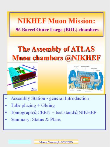
The Assembly of ATLAS Muon chambers _at_NIKHEF
NIKHEF Muon Mission 96 Barrel Outer Large (BOL)
chambers
- Assembly Station - general Introduction
- Tube placing Gluing
- Tomograph_at_CERN test stand_at_NIKHEF
- Summary Status Plans
2
QC-Wire tension
- Quality Control on drift tubes, specs
- Wire Frequency 27.2 (-1.4)Hz, RMSlt0.3Hz
Principle Lorentz force on current through wire
causes vibration
Drift tube
Frequency RMS 0.17 Hz
Horse-shoe magnet
Tension re-measured just before gluing on
table (checks creep broken wires)
Rejection ltlt1.
s
3
Tube wiring QC
- Drift tubes
- Extruded aluminum drift tubes (3cm)
- Wire (50mm gold-plated tungsten) positioned
by two end-plugs
Endplug
- QC on drift tubes, specs
- Wire position Z,Ylt25mm
- Wire tensiongt
- frequency 27.2-1.4 Hz, RMSlt0.3Hz
- Leak rate lt2.5 10-8 bl/s
- HV check lt20nA _at_3500V
4
QC-Wire position
Wire position Spec Y,Zlt25mm
For BOL-1 All tubes checked In future Fast
pre-check endplug
Rejection ltlt1 2 tubes with Zgt 50um (1
checked no twister)
cut
cut
No twister to position wire
s
5
QC-Wire tension
- Quality Control on drift tubes, specs
- Wire Frequency 27.2 (-1.4)Hz, RMSlt0.3Hz
Principle Lorentz force on current through wire
causes vibration
Drift tube
Frequency RMS 0.17 Hz
Horse-shoe magnet
Tension re-measured just before gluing on
table (checks creep broken wires)
Rejection ltlt1.
s
6
QC-Leak Rate HV
- Quality Control
- Leak rate lt2.5 10-8 bl/s
- HV lt 20nA at 3400V
Principle
HV
Drift tube (1 He)
Vacuum chamber
He sniffer
Automated Matrix for 80 tubes
s
7
QC-Leak Rate
Leak-rate
Leak rate is low from 3bar to 2bar takes several
years!!
spec
Rejection 1 (!)
10-6 bl/s
- 3 tubes inspected
- 1 physical hole in aluminum
- 2 dust on O-ring
s
8
QC-HV
- A typical Matrix fill
Tube with excessltltspec.
Measure 5hrs. Average last 3hrs
Current (nA)
Gauge
Tube nr
s
9
Chamber Assembly
- Spacer monitored by RASAS
Situation mid 2000
No Flexo
In-plane lens
NIKHEF Comb
longbeam
RASAS tower
Xplate
In-plane mask
Frascati comb
Ear with sphere and RASAS-MASK
Sphere tower with changeable block to adapt to
tube layers
West side has expansion length o 0.1m in Xras
s
10
RASAS Monitors
Monitor positioning during assembly by RASAS
monitor
Support ear which holds the mask
xplate
Changeable blocks
The RASAS tower which holds the camera and lens
Measured temperatures explain (small) drift
s
11
Temperature Stability
- Aluminum expands 24um/ oC/m, Granite 7um/ oC/m
- Under normal conditions, temperature stable
within -0.4 oC - Test case increase temp. by 1 oC check RASAS
monitors
Free to expand
monitor
granite
Raw 50um
Correct for AL 24um/ oC/m
Correct for granite 7um/ oC/m
s
12
Precision Mechanics
- intrinsic accuracy better than 10um
- Positioning combs and sphere holders
- Tools
- Laser optics (straightness combs),
- silicon sensor (to line up combs),
- Slof (height-meter),
- tilt-meters (check Torque),
- Balmonitor (dZ between multilayers)
The quantities which affect the wire positions
are checked and found to be precise within
10um Granite table has sag of 25um 10um light
on/off
West side has expansion length o 0.1m in Xras
s
13
Assembly Station
- The Balmonitor is a Cross-Plate equipped with
lenses. Each lens is combined with a fork on
the combs to form a RASNIK system
- The Balmonitor measures the Z and Y difference
between Sphere tower and Comb between North and
South. (Z difference between Multilayers) - Additionally the Balmonitor is used to check for
height difference between sphere towers at the
reference and non-reference side (West/East)
West side has expansion length o 0.1m in Xras
s
14
Tube Placing I
Place tubes (with clocking pins) on combs
(Re-)Measure Wire Frequency Run Final-OK
program IF all tubes OK, follow placing scheme
Frequency
Small calibration problem
Specs RMSlt 0.3 Hz BOL1 27.2-0.7 Hz Later
27.2-1.4 Hz
FOK program ensures 72 tubes are OK Tube
numbers and positions stored in dbase
s
15
Tube Placing II
Fix gas jumpers -length differences get
neutralized Spec-0.5mm (FE-cardsground foil)
s
16
Tube Placing QC
Vacuum on Remove clocking pins, loosen gas
jumpers Check precision Guido Laser (not
automated yet)
Y deviation (mm)
Tube Position (South)
Tube Position (North)
s
17
Sag Compensation
Dry Check Position spacer (tube layers) on the
table Check sag-compensation (not automated yet)
Strip
Actual Gluing Chamber is pre-positioned 1mm
strips under sphere blocks50 sag-comp. Then
strips are removed 80-90 sag-compensation
s
18
Sag Compensation
- Xplate sag before and after compensation
Chamber up
Chamber (upside) down
Understood within -10mm
After sag adjustment we observe (almost)
symmetric sags for chamber up and down
positions-gt no stress
s
19
Gluing
Tube diameter 3cm Distance 65mm
2 x glue units 2x3 glue nozzles
automated
50um tape on Bessel points
Central rope, Glu 2019
Side rope, Glu 2011
s
20
Gluing BOL
s
21
Monitoring
badly positioned -gt action!
Compensation on
- 3 systems monitor chamber during assembly
- RASAS system (include temperature check)
- In-Plane system
- RASNIKS on cross-plates (sag)
Plot xplare rasnik
Monitoring system actions not yet user
friendly.
s
22
Gluing BOL-0
- RASAS monitors
Global Z
- Relatively large Z movement layer 6 (spacer
floats on glue?)
Lever arm in stacking block
Global Y (up)
- Stability in Y appears good
s
23
The road to BOL-1
- From 1st tube layer to 6th tube layer took 14
days (spacer not counted) - With optimal/parallel preparation the present
scheme would allow a 7 day production cycle - Infrastructure and manpower-gt
- 10 working-days/chamber
24
Power Outage- BOL1
Power outage Amsterdam, during curing of layer
5 Chamber immediately covered with foil (sag
compensation remained on vacuum probably ok No
indications for damage
s
25
The BOL-0
- The BOL-0 was mechanically
- finished Dec 5th 2000
- Next, studies
- X-ray scan
s
26
Test _at_CERN inTomograph
Analysis of Martin Woudstra
Wire positions RMS 16mm
s
27
Parameters
Zpitch wires 30.0354mm (30.0353
expected) Ypitch wire-planes 26.026mm (26.011
expected). Especially between two inner layers we
have a larger pitch. Inelastic deformation during
gluing? dY multilayers 75mm. Hard to
understand. ALL chamber scanned at CERN have
deviations in this parameter?! dZ multilayers
12mm. We expected deviations of this order,
based on Balmonitor measurements
- Relevant Parameters (goal 20mm)
- RO side s15.8mm HV side s16.1mm
s
28
Expected shifts
s
29
Test stand
Like cosmic ray setup at CERN (shutdown in 2000)
- DATCHA
Test of alignment principle with prototype muon
sector, using cosmic tracks --gt 10mm on
sagitta
s
30
Test stand _at_NIKHEF
- Tests five chambers using cosmic rays (end 2001)
- Checks wire positions
- Checks DCS DAQ
Trigger modules, consisting of 50cm iron, with
two layers scintillator. Ecutgt1GeV Expected rate
100Hz
s
31
Status Plans
- Finished BOL-0 at NIKHEF (dec. 5th 2000) with
high mechanical precision (16mm RMS) - Quality Control Tube Assembly automated
- Production of tubes started May 2001
- First chamber, BOL1, produced!
- Automate stepsQC chamber assembly
- Cosmic ray setup end 2001.
32
Documentation Web Page
s
33
Gluing BOL-0
- Guido laser test indicate tube heights in combs
lt10um. - Stability Xplates during gluing
Layer 1
Yrasnik2 x Sag
Layer 1 dSag7um
Layer 2
Start glue
Layer 3
Layer 2 dSag10um
- The sag of the xplates in layer 1 and 2 change in
time. Glue crimp? Temperature? - Layer 3,4,5,6 Sag stable
s
34
Gluing BOL-0
- In-Plane and Xplate monitors
- X-inplane very stable
- Y-inplane alternates with chamber orientation,
because off granite sag of 30um
down
down
up
up
Cross-plate sag. For chamber up (down)
positions, a negative (positive) sag points down.
s
35
BOL-0
Thickness Multi-layers BOL0 has tape between
tubes at one side
Much work..
2 layers
- Tubes press glue away?
- Tubes deform?
- Affects precision praxial platforms!
3 layers
s
36
BOL-0
Heat Studies (No flexoos in BOL-0)
The BOL-0 was covered with heat blankets,
producing 50W/m2
Inplane
Yrasnik 2 x sag
Gradient between MLs 2.5 to 4 oC Sag of Chamber
200um ? 50 to 80 um/oC acceptable Sag of
xplate 25um ? 6 to 10 um/oC acceptable
s
37
Gluing BOL-0
- Result for side (106) and central (103) ropes
Central rope
Central rope
Central rope
Central rope
Central rope, sometimes bad (stability glue unit?)
38
Assembly Station
- Granite table 6m x 2.5m
Situation mid 99
East Z
Up Y
North X
- Three bare Cross-Plates are positioned on the
station, carried by sphere holders - The combs which will support the tubes are also
visible - In the background wiring station, Quality
Control setup(s)
West side has expansion length o 0.1m in Xras
s
Recommended
CrystalGraphics Presentations


