
ITEC 3010 PowerPoint PPT Presentation
1 / 84
Title: ITEC 3010
1
ITEC 3010 Systems Analysis and Design,
I LECTURE 5 Modeling System Requirements
Prof. Peter Khaiter
2
Lecture Outline
- Defining System Requirements
- CRUD Operations
- Events and Use Cases
- Things and System Requirements
- Data Entities
- Entity-Relationship Diagram (ERD)
- Class Diagram
3
The Activities of the Analysis Phase
4
Define System Requirements
- Activity of the analysis phase
- Involves a variety of models to document
requirements - Two key concepts identifying functional
requirements (in traditional approach and
object-oriented approach) - Use cases and the events that trigger them
- Things in the users work domain
5
Definitions
- Use Case -- An activity the system performs in
response to a user request - Techniques for identifying use cases
- User goal technique by talking to users to get
their description of goals in using the system - Identify categories of users
- Each goal at the elementary business process
(EBP) level is a use case - EBP a task performed by one user, in one place
in response to a business event, that adds
measurable business value, and leaves system and
data in consistent state
6
Identifying Use Cases with the User Goal Technique
7
CRUD Technique
- Four operations with data
- Create
- Read
- Update
- Delete
- By looking at types of data (data entities or
domain classes), e.g., Customer, OrderItem
identify use cases that support CRUD operations
8
Use Case Based on CRUD Technique
9
Event Decomposition Technique
- Event an occurrence at a specific time and
place and which requires system to respond - Business events trigger elementary business
processes (EBPs)? - EBPs are at correct level of analysis for use
cases - Identify business events to decompose system into
activities/use cases
10
The Background to Event Concept
- Structured analysis first adapted the concept of
events to real-time systems in the early 1980s. - Real-time systems (e.g., process control system,
reactors, aerospace, etc.) require the system to
react immediately to events in the environment
(events like chemical vat is full, boiler
overflowing) - The concept did not find application to business
system at that time, but had been used in
technical systems - Now the concept extended to business applications
since they have become more interactive (can be
thought of as real-time systems) - Information engineering approach now
uses it - Very important in object-oriented
approach
11
Types of Events
- External
- Outside system
- Initiated by external agent or actor (e.g.,
Customer places an Order) - Temporal
- Occur as result of reaching a point in time
- Based on system deadlines (e.g., Produce a
biweekly payroll) - State
- Something inside system triggers processing need
(e.g., Reorder point reached)
12
Events and Use Cases in Account Processing System
13
External Event Checklist
14
Temporal Event Checklist
15
Identifying Events
- Events versus conditions and responses
- It can be difficult to distinguish between an
event and the sequence of conditions that lead to
it (e.g., sequence of actions leading to buying a
shirt see Figure, next slide) - Also it may be hard to distinguish between an
external event and the systems response (e.g.
customer buys the shirt, system requests credit
card number, the customer supplies the credit
card is not an event for the information
system, but just a part of interaction that
occurs while completing the original transaction,
i.e. the customer buying the shirt which is the
real event) - Way to determine whether an occurrence is an
event - Ask whether any long pauses or intervals occur
(i.e., can the system transaction be completed
without interruption? Or, is the system at rest
again waiting for another transaction? Once a
transaction starts there are no significant stops
till it is done.
16
Sequence of Actions Leading Up to Only One Event
Affecting the System
17
Identifying Events
- The Sequence of Events Tracing a Transactions
Life Cycle - It is often useful in identifying events to trace
the sequence of transactions for a specific
external agent or actor - For Rocky Mountain Outfitters example all the
possible transactions resulting from one new
customer (see Figure, next slide) - Customer wants a catalog
- Customer asks for information about
availability - Customer places an order
- Customer wants to check status of an
order - Customer wants to change his/her
address - Customer may want to return an item
18
Sequence of Transactions for One Specific
Customer Resulting in Many Events
19
Identifying Events
- Technology-Dependent Events and System Controls
- Some important events do not concern directly
users or transactions (e.g., design of system
controls) - System controls are checks or safety procedures
to protect the integrity of the system. For
example - Logging on to a system (for security
reasons) - Controls for keeping integrity of a
database (e.g., backing up the data every day) - Controls are added to the system during design
but should not be considered during analysis (it
adds to the requirements details that the users
are not typically very concerned about) - To help decide which events apply to controls we
assume that technology is perfect (never the
case!)
20
The Perfect Technology Assumption
- The perfect technology assumption states that
- During analysis we should focus on events that
the system would be required to respond under
perfect conditions, i.e. with equipment never
breaking down, capacity for processing and
storage being unlimited and people operating the
system being completely honest and never making
mistakes. Assuming the perfect technology (e.g.,
the disk will never crash), the analysts can
eliminate events like Time to back up the
database. - During design phase we deal with these issues and
events from a non-perfect world point of view,
e.g. events like Time to back up the database
and add these controls (Figure, next slide lists
some of events that can be deferred until the
design phase).
21
Events Deferred Until the Design Phase
22
External Events for RMO Customers and Departments
23
Temporal Events for RMO
24
Documenting the Events
- An event table represents events and their
details each row contains information about one
event, each column represents a key piece of
information about the event (see next slide
showing event table about an event Customer
wants to check item available) - Each event is characterized by
- The trigger an occurrence that tells the
system that an event has occurred (either the
arrival of data needing processing or of a point
in time) E.g., a customer places an order, the
new order detail are provided as input - The source an external agent or actor that
supplies data to the system - The activity behavior that the system performs
when an event occurs (the systems reaction) - The response an output, produced by the system
that goes to a destination - The destination an external agent or actor
that receives data from the system
25
Information about Each Event in an Event Table
26
RMO Event Table
27
Use Case Descriptions
- Use case description a description of the
processing steps for a use case - Actor a person or thing that uses the system
and interacts with the system always outside of
the automation boundary, but may be part of the
manual portion - Scenario or Instance a particular set of
internal steps/activities to complete a business
process representing a unique path of the use
case - Preconditions conditions that must be true
before a use case begins - Postconditions - conditions that must be true
upon completion of the use case
28
Use Case Descriptions
- Three levels of details
- Brief description (small, well-understood
applications, simple scenario, no exception
conditions) - Intermediate description (includes internal flow
of activities, each flow of activities is
described individually, exception conditions) - Fully developed description (most formal method
First and second parts identify the use cases
and scenarios within use cases Third part
triggering event that initiate the use case
Fourth part brief description Fifth part
actors Sixth part cross reference to other use
cases Two Final compartments detailed flow of
activities, alternative activities and exception
conditions
29
Brief Description
30
Intermediate Description
31
Fully Developed Description
32
Things and System Requirements
- Define system requirements by understanding
system information that needs to be stored - In Traditional approach store information about
data, i.e., things in the problem domain that
people deal with when they do their work (e.g.,
products, orders, invoices) - In OOA similar to the objects, i.e., external
agents or actors that interact with the system
(e.g., customers)
33
Types of Things
34
Just for Fun!
http//www.getfunnypictures.com/crt054.html
A new iMac product
35
Types of Things
Tangible things are the most obvious (e.g.,
airplane, book, vehicle, document, worksheet)
Roles played (e.g., a role played by a person,
such as employee, customer, doctor or patient,
end user) Organizational units (e.g., division,
department, section, task force, work group)
Devices (e.g., sensor, timer, controller,
printer, disk drive) Incidents, events, or
interactions can be considered as the things
(e.g., information about an order, a service
call, a contract, or an airplane flight an order
is a relationship between a customer and an item
of inventory) Sites/locations (e.g., a
warehouse, a store, a branch office)
36
Things in Domain
- A way to identify things of interest
- The analyst can identify types of things by
thinking about each event in the event list and
asking what types of things are affected that the
system needs to know about, e.g. when a customer
places an order we need to know about the
following - The customer
- The items ordered
- Details about the order (e.g., date and
payment terms)
37
Procedure for Developing an Initial List of
Things
- Step 1 Using the event table and information
about each use case, identify all nouns (e.g.,
customer, product item, order, transaction, back
order, shipping, etc) - Step 2 Using other information from existing
systems, current procedures, and current reports
or forms, add items or categories of information
needed (e.g., price, colour, size, style, season,
inventory quantity, payment method, shipping
address, etc called attributes) - Step 3 Refine list and record assumptions or
issues to explore - Questions to ask to include it, exclude
it, or research it
38
Questions to decide
- Questions to ask to decide whether you should
include, are - - Is it unique thing the system needs to
know about? - - Is it inside the scope of the system?
- - Does the system need to remember more
than one of these items? - Questions to ask to decide whether you should
exclude, are - - Is it really a synonym for some other
thing you have identified? - - Is it just an input that results in
recording some other information you have
identified? - Questions to ask to decide whether you should
research, are - - Is it likely a specific piece of
information (attribute) about some other thing
you have identified? - Is it something that you might need if
assumptions change?
39
RMO Example Things
40
Partial List of Things for RMO
41
Characteristics of Things
- Relationship
- Naturally occurring association among specific
things - Occur in two directions
- - A customer places an order (one
direction) - - An order is placed by a customer (other
direction) - Number of associations is cardinality or
multiplicity (must be established for each
direction of the relationships) - Attribute
- One specific piece of information about a thing
42
Relationships Between Things
43
Cardinality/Multiplicity of Relationships
Cardinality means the number of associations
that occur between specific things Cardinality
is established for each direction of the
relationship. Multiplicity is a synonym for
cardinality often used with the object-oriented
approach Also may be important to know the
range of possible values of the cardinality (the
minimum and maximum cardinality). E.g., a
customer might not ever place one order (zero
associations), or place one order (one
association) In some cases, at least one
association is required (a mandatory as opposed
to optional relationships) A one-to-one
relationship can also be refined to include
minimum and maximum cardinality (e.g. the order
is placed by one customer it is impossible to
have an order if there is no customer. Therefore,
one is the minimum cardinality, making the
relationship mandatory)
44
Cardinality/Multiplicity of Relationships
45
Cardinality/Multiplicity of Relationships
Kinds of Relationships Binary relationship is a
relationship between two different types of
things (e.g., between a customer and an order)
Unary (recursive) relationship is a relationship
between two things of the same type (e.g., one
person being married to another person or one
department reports to another one) Ternary
relationship is a relationship between three
different types of things (e.g., one order
associated with a specific customer plus a
specific sales representative) n-ary
relationship is a relationship between n (any
number) different types of things
46
Attributes of Things
- Attribute is one piece of specific information
about a thing (e.g., a customer has a name, phone
number, credit limit, etc. each of these is an
attribute of a customer) - The analyst has to identify the attributes of
each thing that the system needs to store - Identifier (or key) is an attribute that
uniquely identifies a thing (e.g., a persons
social insurance number, or an invoice or
transaction number) - Compound attribute is an attribute that
contains a collection of related attributes
(e.g., a customer full name is made up of first
name, middle name, last name and possibly
nickname)
47
Attributes and Values?
48
Data Entities
- Data entities are the things the system needs
to store information about in the traditional
approach to information systems (entities are
things like customers and order) - The data entities, the relationship between
data entities and the attributes of data entities
are modeled using an entity-relationship diagram
(ERD) - Computer processes interact with these data
entities, creating them, updating attribute
values and associating one with another - We can think about things as objects that
interact in the system - Objects in the work environment of the user
(called also problem domain) in the
object-oriented approach are often similar to
data entities in the traditional approach - The main difference the objects do the work in
the system, but do not just store information
(i.e. they have behavior as well as attributes) - With the object-oriented approach, each
specific thing is an object (John, Mary, Bill)
and the type of thing is called class (in this
case, customer)
49
Data Entities vs. Objects
50
The Entity-Relationship Diagram (ERD)
Data storage requirements include the data
entities, their attributes and the relationships
among the data entities. The model used to
define the data storage requirements is called
the entity-relationship diagram (ERD) ERD
Notation Rectangles represent data entities
Lines connecting rectangles show relationships
among data entities
51
ERD
52
Cardinality Symbols of Relationships for ERD
53
Expanded ERD with Attributes
54
Transactions for Expanded ERD
55
ERD with Many-to-Many Relationship
56
Many-to-Many Relationship Converted to
Associative Entity to Store Grade Attribute
57
ERD The RMO Case
Each customer can place zero or more orders
Each order can have one or more order items
Each order item is for specific inventory item
Each inventory item is associated with a product
item that describes the item generally(vendor,
description, season, price, special price) Each
product item is contained in one or more
catalogs The catalog offers packages (shirt,
pains and belt) at a reduced price A package
contains product items A catalog contains zero
or more packages (an optional relationship), but
a package must include at least one product item
(a mandatory relationship) Each order item is
part of a shipment A shipment may contain many
order items Each shipment is shipped by one
shipper Each order associated with one or more
order transactions (An order transaction is a
record of a payment or a return for the order.
One order transaction is created when the
customer initially pays for the order, the
customer might return an item, requiring a refund
and another transaction)
58
RMO Customer Support System ERD
59
The Domain Model Class Diagram
- Unified Modeling Language (UML) diagram
- de facto standard for models used with
object-oriented system development - Domain model class diagram is a model to show
classes of objects - Models things in the users work domain
- Used to define requirements for OO (very similar
to entities in ERD) - Class is the type or classification to which all
similar objects belong (e.g. guitar and violin
objects both belong to class stringed
instruments)
60
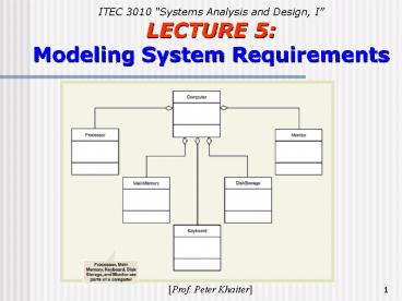
UML Class Symbol
- The class symbol is a rectangle
- The top section of the rectangle is the name of
the class - The middle section is the attributes of the class
- The bottom section lists the methods of the class
(methods define the behavior of objects of the
class). Methods are not always shown as far as
they are standard.
61
UML Class Symbol
62
Class Diagram
- Classes, associations among classes and
attributes of classes are modeled using a class
diagram - The class diagram shows some of the behaviors of
objects of the class, called method - Methods of a class are the behaviors all objects
in the class are capable to do. - A behavior is an action that the object processes
itself, when asked to do so by sending it a
message from another object - Since each object contains values for attributes
and methods for operating on those attributes
(plus other behaviors), an object is said to be
encapsulated (i.e., a self-contained and
protected unit)
63
Simple Domain Model Class Diagram
64
Simple Domain Model Class Diagram (continued)
- No methods shown in domain model
- Domain classes are not software classes
- Very similar to ERD
- UML and domain model can be used in place of ERD
in traditional approach
65
Multiplicity of Associations
66
University Course Enrollment Domain Model Class
Diagram
67
Refined Model with Association Class and Grade
Attribute
68
More Complex Class Concepts
- Generalization/specialization hierarchies
- Inheritance
- Aggregation
69
Generalization/Specialization
- Generalization means grouping similar types of
things (e.g., motor vehicles group cars, trucks
and tanks. They share certain general features
(e.g., wheels, engine, etc.), so motor vehicle is
a more general class) - Specializations are judgments that categorize
different types of things (e.g., sports car is a
special type of car) - A generalization/specialization hierarchy is used
to structure (or rank) things from the more
general down to the more special - Each class has a more general class above it a
superclass - A class may have a more specialized class below
a subclass
70
A Generalization/Specialization Class Hierarchy
for Motor Vehicles
71
A Generalization/Specialization Class Hierarchy
for RMO Orders
72
Inheritance
- Inheritance is a concept that allows subclasses
to share characteristics of their superclasses - E.g. a sports car has everything a car has
(e.g., 4 wheels and an engine, which it inherits
from the class car which is above it) - The sports car then specializes
- E.g., has a sports option, racing wheels,
etc. - In the object-oriented approach, inheritance
is a key concept that is possible because of
generalization/specialization hierarchies (these
hierarchies are often called inheritance
hierarchies)
73
Whole-Part Hierarchies
- Whole-part hierarchies relationships that
structure classes by components - Aggregation whole-part relationships between
and object and its removable parts - Parts can exist separately
- Like car and its tires
- Composition whole-part relationships between
and object and its non-removable parts. - Parts cannot exist separately
- Like Hand is composed of fingers and thumb
74
Whole-Part Aggregation Relationships
75
Class Diagram Example Bank Account
Bank account system includes a
generalization/specialization hierarchy
Account is the superclass SavingsAccount
and CheckingAccount are subclasses of Account
A triangle on the line connecting classes
indicates inheritance (the subclasses inherit
attributes and behaviors from the superclass
Account like having an account number) But
Savings and Checking accounts are also
specialized A SavingsAccount knows how to
calculate interest but a checking account doesnt
(so they have different methods and attributes,
although they share things they inherit from
class Account)
76
Class Diagram Example Bank Account
The Customer class and the Account class are
associated Each customer can have zero or
more accounts (the diagram shows the minimum and
maximum cardinality on the line connecting the
classes, and the asterisk means many
Each account is owned by one and only one
customer The SavingsAccount and CheckingAccount
classes inherit the association with the Customer
class The Account class is an abstract class
(i.e., the class that cannot be instantiated,
existing only to allow subclasses to inherit its
attributes, methods and associations) shown in
italics SavingsAccount, CheckingAccount and
Customer are examples of class are concrete
classes that can be instantiated (i.e., objects
can be created)
77
A bank account system class diagram
78
Association Class
- If the association itself has attributes and/or
methods, it can be represented by an association
class (represents many-to-many relationships) - Multiplicity of the association between
CourseSection and Student is many-to-many. A
dashed line connects the association line to the
association class named CourseEnrollment that has
the grade attributes
79
University course enrollment class diagram with
an association class
80
The RMO Domain Class Diagram
- A generalization/specialization hierarchy
is included to show three types of orders web
order, telephone order and mail order, which
share the attributer listed for Order class, but
each special type of order has some additional
attributes - This diagrams shows no methods
- The initial class diagram developed during
the systems analysis phase includes no methods.
As behaviors of objects are further developed
(during analysis and design) methods are added
81
RMO Domain Model Class Diagram?
82
TA vs. OOA Requirements modeling
The requirements models are quite different
depending on approach used by the team
traditional or object-oriented (the two key
concepts events and things) Traditional
approach based on the event table creates a set
of data flow diagrams (DFDs) the
entity-relationship diagram (ERD) defines the
data storage requirements that are included in
the DFDs, views a system as a collection of
processes. When the process executes it interacts
with data. So, emphasizes processes, data,
input/outputs Object Oriented approach based
on the event table creates class diagrams, views
a system as a collection of interacting objects
with their own behaviour (methods). There are NO
conventional processes and data files, just
interacting objects
83
Requirements Models in TA and OOA
84
Readings
Todays lecture Chapter 5 Modeling System
Requirements For next lecture Chapter 6 The
Traditional Approach to Requirements
Thank you !!!
Recommended
