
COMPLEXITY EFFECTIVE SUPERSCALAR PROCESSORS PowerPoint PPT Presentation
Title: COMPLEXITY EFFECTIVE SUPERSCALAR PROCESSORS
1
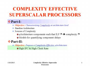
COMPLEXITY EFFECTIVE SUPERSCALAR PROCESSORS
- Part-I
- Objective Characterizing Complexity at
architecture level - Baseline Architecture
- Sources of Complexity
- ?Architecture components such that ILP ? ?
complexity ? - Models for quantifying component delays
- Part-II
- Objective Propose a Complexity-Effective
?Architecture - High IPC High Clock Rate
2
CHARACTERIZING COMPLEXITY
- Complexity Delay through critical path
- Baseline Architecture?
- Defining Critical Structures
- Method for Quantifying Complexity
- Analysis of Critical Structures
- ltMostly from 2gt
3
BASELINE ARCHITECTURE
- Superscalar, o-o-o execute, in order complete
- MIPS R10000, DEC Alpha 21264
4
BASELINE ARCHITECTURE
- Fetch
- Read Fetch-Width Instr-s/clk from I
- Predict Encountered Branches
- Send to decoder
5
BASELINE ARCHITECTURE
- Decode
- Decode instructions into opsubopimm.operands
etc.
6
BASELINE ARCHITECTURE
- Rename
- Rename the logical operand registers
- Eliminate WAR and WAW
- Logical register ? physical register
- Dispatch to Issue Window (Instruction Pool)
7
BASELINE ARCHITECTURE
- Issue Window Wakeup-Select Logic
- Wait for source operands to be ready
- Issue instructions to exec. Units if ? Source
operands ready functional unit available - Fetch operands from Regfile or bypass
8
BASELINE ARCHITECTURE
- Register File
- Hold the physical registers
- Send the operands of currently issued
instructions to exec. Units or bypass
9
BASELINE ARCHITECTURE
- Rest of Pipeline
- Bypass Logic
- Execution Units
- Data Cache
10
OTHER ARCHITECTURES
- Reservation Station Model
- Intel P6, PowerPC 604
11
Baseline vs. Reservation Station
- Two Major Differences
- Baseline Model
- All reg. values reside in physical reg-file
- Only tags of operands broadcast to window
- Values go to physical reg-file
- Res. Station Model
- Reorder buffer holds speculative values reg-file
holds commited values - Completing intsr-s broadcast operand values to
reservation station - Issued instr-s read values from res. station
12
CHARACTERIZING COMPLEXITY
- Complexity Delay through critical path
- Baseline Architecture
- Defining Critical Structures?
- Method for Quantifying Complexity
- Analysis of Critical Structures
- ltMostly from 2gt
13
CRITICAL STRUCTURES
- Structures with Delay ? Issue Width(IW) Issue
Window(WinSize) - Dispatch Issue related structures
- Structures that broadcast over long wires
- Candidate Structures
- Instruction Fetch Logic
- Rename Logic
- Wakeup Logic
- Select Logic
- Register File
- Bypass Logic
- Caches
14
Instruction Fetch Logic
- Complexity ? Dispatch/Issue Width
- As instr. Issue width ? ? Predict Multiple
branches - Non contiguous cache blocks need to be fetched
and compacted - Logic Described in 5
- Delay Models to be developed
15
Register Rename Logic
- Map Table Logical to Physical Register Mapping
- IW ? ? Number of map table ports ?
- Dependence Check Logic Detects true dependences
within current rename group - IW ? ? Depth of Dep. Check Logic?
- Delay ? Issue Width
16
Wakeup Logic
- Part of Issue Window
- Wake up Instr-s when source operands ready
- When an instr. Issued, its result register tag
broadcast to all instructions in issue window - WinSize ? ? Broadcast Fanout ? Wire Length ?
- IW ? ? Size of each window entry ?
- Delay ? Issue Width Window Size
17
Selection Logic
- Part of Issue Window
- Select Instr-s from ones with all source operands
ready if available FU exists - Selection Policies
- WinSize ? ? Search Space ?
- of FUs ? ? of Selections?
- Delay ? Window Size of FUs Selection
Policy
18
Register File
- Previously studied in 6
- Access Time ? of Physical registers of
readwrite ports - Delay ? Issue Width
19
Data Bypass Logic
- Result Wires Set of wiresto bypass results of
completedbut not committed instr-s - of FUs ? ? wire lengths?
- Pipeline Depth? ? of wires? load on wires?
- Operand MUXes select appropriate values to FU
I/p ports - of FUs ? ? Fan-in of MUXes?
- Pipeline Depth ? ? Fan-in of MUXes?
- Delay ? Pipeline depth of FUs
20
Caches
- Studied in 7 8
- 7 gives detailed low level access time
analysis - 8 based on 7s methodology, with finer detail
- Delay ? Cache Size Associativity
21
CHARACTERIZING COMPLEXITY
- Complexity Delay through critical path
- Baseline Architecture
- Defining Critical Structures
- Method for Quantifying Complexity ?
- Analysis of Critical Structures
- ltMostly from 2gt
22
QUANTIFYING COMPLEXITY
- Methodology
- Key Pipeline Structures studied
- A representative CMOS design is selected from
published alternatives - Implemented the circuits for 3 technologies
- 0.8?, 0.35? 0.18 ?
- Optimize for speed
- Wire parasitics in delay model
- Rmetal, Cmetal
23
QUANTIFYING COMPLEXITY
- Technology Trends
- Shrinking Feature Sizes ? Scaling
- Feature size scaling 1/S
- Voltage scaling 1/U
- Logic Delays
- CL Load Cap. 1? 1/S
- V Supply Voltage 1? 1/U
- I Average charge/discharge current 1? 1/U
- Overall Scale factor 1/S
24
QUANTIFYING COMPLEXITY
- Wire Delays
- L wire length
- Intrinsic RC delay ?
- Rmetal Resistance per unit length
- Cmetal Capacitance per unit length
- 0.5 1st order approximation of distributed RC
model
25
QUANTIFYING COMPLEXITY
- Scaling Wire Delays
- Metal Thickness doesnt scale much
- Width ? 1/S
- Rmetal ? S
- Fringe Capacitance dominates in smaller feature
sizes - Cmetal ? S
- (Length scales with 1/S)
- Overall Scale factor S.S.(1/S)2 1
26
CHARACTERIZING COMPLEXITY
- Complexity Delay through critical path
- Baseline Architecture
- Defining Critical Structures
- Method for Quantifying Complexity ?
- Analysis of Critical Structures?
- ltMostly from 2gt
27
COMPLEXITY ANALYSIS
- Analyzed Structures
- Register Rename Logic
- Wakeup Logic
- Selection Logic
- Data Bypass Logic
- Analysis
- Logical function
- Implementation Schemes
- Delay in terms of ?Architecture Paramaters?
- Issue Width
- Window Size
28
Register Rename Logic
- Map Table Logical Name ? Physical Reg.
- Multiported
- Multiple instr-s with multiple operands
- Dependence Check Logic Compare each source
register to dest. Reg-s of earlier instr-s in
current set - Multiported
- Multiple instr-s with multiple operands
- Shadow Table Checkpoint old mappings to recover
from branch mispredictions
29
Register Rename Logic
- -
If Src Reg, Read From TableIf Dest Reg, add to
table
Go to issue window
Decoded Instructions
!
30
Map Table Implementation
- Implementation ? RAM or CAM
- RAM (Cross Coupled inverters)
- Indexed by Logical reg-s of entries
- Entries Physical reg-s
- Shift-Register for Checkpointing
- CAM
- Associatively searched with logical reg
designator - Entries Logical Reg Valid Bit
- of entries of physical registers
- CAM vs RAM
- Similar performance ltOnly RAM analyzedgt
31
Dependence Check Logic
- Accessed in Parallel with Map Table
- Every Logical Reg compared against logical dest
regs of current rename group - For IW2,4,8, delay less than map table
32
Rename Logic Delay Analysis
- Map Table ? RAM scheme
- Delay Components
- Time to decode the logical reg index
- Time to drive wordline
- Time to pull down bit line
- Time for SenseAmp to detect pull-down
- MUX time ignored as control from dep. Check logic
comes in advance
33
Rename Logic Delay Analysis
- Decoder Delay
- Predecoding for speed
- Length of predecode lines
- Cellheight Height of single cell excluding
wordlines - Wordline spacing
- NVREG of virtual reg-s
- x3 3-operand instr-s
34
Rename Logic Delay Analysis
- Decoder Delay
- Tnand Fall delay of NAND
- Tnor rise delay of NOR
- Rnandpd NAND pull-down channel resistance
- Predecode line metal resistance (NAND --- NOR)
- 0.5 due to distributed RC model for delay
- Ceq diff-n Cap. Of NAND gate Cap. Of NOR
interconnect Cap.?
35
Rename Logic Delay Analysis
- Decoder Delay
- Substituting PredecodeLineLength, Req, Ceq ?
Tdecode - c2 intrinsic RC delay of predecode line
- c2 very small ?
- Decoder delay linearly dependent on IW
36
Rename Logic Delay Analysis
- Wordline Delay
- Turn on all access transistors (N1 in cell
schematic p.32) - PREGwidth phys. reg designator width
- Rwldriver pull-up res. Of driver
- Rwlres resistance of wordline
- Cwlcapcapacitance on word line
37
Rename Logic Delay Analysis
- Wordline Delay
- Total Wordline Capacitance
- Total Gate Cap. of access transistors wordline
wire cap. - B maximum of shadow mappings
(Fall Time of inv. Rise time of driver)
(0.5 for distributed RC)
38
Rename Logic Delay Analysis
- Wordline Delay
- Substituting WordLineLength, Rwlres, Cwlcap ?
Twordline - c2 intrinsic RC delay of wordline
- c2 very small ?
- Wordline delay linearly dependent on IW
39
Rename Logic Delay Analysis
- Bitline Delay
- Time from wordline going Hi (Turning on N1) ?
Bitline going below sense Amp threshold - c2 very small ?
- Bitline delay linearly dependent on IW
40
Rename Logic Delay Analysis
- Sense Amplifier Delay
- Sense Amp design from 7
- Implementation ind. of IW
- Delay varies with IW
- Delay ? slope of I/p (bitline Voltage) ?
- Delay ? bitline delay ?
- SenseAmp delay linearly dependent on IW
41
Rename Logic Spice Results
- Total delay increases linearly with IW
- Each Component shows linear increase with IW
- Bitline Delay gt Wordline Delay
- Bitline length ? of Logical reg-s
- Wordline length ? width of physical reg designator
- Feature size ? ? increase in bitlinewordline
delay with increasing IW ? - 0.8? IW 2?8 ? Bitline delay ? 37
- 0.18? IW 2?8 ? Bitline delay ? 53
42
Wakeup Logic
- Updating source dependences for instr-s in issue
window - CAM, 1 instr-n per entry
- When an instr-n produces its result, tag
associated with the result is broadcast to issue
window - Each instr-n checks the tag, if matches ?sets
the corresponding operand flag - 2 operand/instr-n ? 2xIW comparators / entry
43
Wakeup Logic
OverallWakeup Logic
1 Bit XNOR
DISCUSS POSSIBLE DELAY ANALYSIS
Go along for all tag bits
Single bit CAM cell(Compares single bit of Tag
data- with the newcoming result tags)
44
Wakeup Logic Delay Analysis
- Critical Path Mismatch ? Pull ready signal low
- Delay Components
- Tag drivers ? drive tag lines - vertical
- Mismatched bit pull down stack ? pull matchline
low horizontal - Final OR gate ? or all the matchlines of an
operand tag - Ttagdrive ? Driver Pullup R Tagline length
Tagline Load C - Intermediate equations here
- Quadratic component significant for IWgt2 0.18?
45
Wakeup Logic Delay Analysis
- Ttagmatch ? Pulldown Stack Pulldown R Matchline
length Matchline Load C - Intermediate equations here
- TmatchOR ? Fan-in (Delay of a gate ? Fan-in2)
- ltWorst Case Fan-in2 RCgt
- Quadratic component Small for both cases
- Both delays linearly dependent on IW
46
Wakeup Logic Spice Results
- 0.18? Process
- Quadratic dependence
- Issue width has greater effect ? increase all 3
delay components - As IW WinSize ? together ? delay actually
changes like THIS
- Delay wrt Window size Issue width
47
Wakeup Logic Spice Results
- 8 way 0.18? Process
- Tag drive delay increases rapidly with WinSize ?
- Match OR delay constant
- Delay Breakups for various WinSizes
48
Wakeup Logic Spice Results
- 8 way 64 entry window
- Tag drive and Tag match delays do not scale as
well as MatchOR delay - Match OR ? logic delay
- Others ? also have wire delays
- Delay Breakups for different feature sizes
49
Wakeup Logic Spice Results
- All simulations have max WinSize 64
- Larger Window ? Tagline RC delay ? ? (Tagline RC
delay ? WinSize2) - For larger windows ? Use Window Banking
- Reduces Tagline length
Improves RC Delay by x(1/4)
50
Selection Logic
- Chooses ready instructions to issue
- Might be up to WinSize ready instr-s
- Instr-s need to be steered to specific FUs
- I/p ? REQ
- Produced by wakeup logic when all operands ready
- 1 per instr-n in issue window
- O/p ? GRANT
- Grants issue to requesting instr-n
- 1 per request
- Selection Policy
51
Selection Logic
For a Single FU
Tree of Arbiters
Location based select policy
GRANT Signals
REQ Signals
Root enabled if FU available
Anyreq raised if any req is Hi, Grant Issued if
arbiter enabled
52
Selection Logic
- Handling Multiple FUs of Same Type
- Stack Select logic blocks in series - hierarchy
- Mask the Request granted to previous unit
- NOT Feasible for More than 2 FUs
- Alternative statically partition issue window
among FUs MIPS R10000, HP PA 8000
53
Selection Logic Delay Analysis
- Delay time to generate GRANT after REQ
- Delay Components
- Time for REQ to propagate instr-n ? Root
- Root Delay
- Time for GRANT to propagate Root ? instr-n
- (L Depth of Arrbiter Tree)
- 4 I/p arbiter cells Optimum ??
- Delay logarithmically dependent on WinSize
54
Selection Logic Spice Results
- Root delay same for each WinSize ?
- L? x2 ? Delay? lt x2
- Logic Delays ?
- Scale well with feature size
- Caution! Wire delays not included!
L4
L3
L2
55
Data Bypass Logic
- Result Forwarding
- Number of possible bypasses
- S pipestages after first result stage 2 I/p FUs
? - Key Delay Component
- Delay of result wires ? bypass length load
- Strongly layout dependent
56
Data Bypass Logic
Commonly Used Layout
Turn on Tri-State A to pass result of FU1 to left
operand of FU0
1 Bit-Slice
57
Data Bypass Logic Delay Analysis
- Delay ? Generic wire delay
- L is dependent on of FUs (IW) FU heights
- Pipeline depth? ? C ? ltNOT implemented in
simulations!gt - Typical FU heights
58
Data Bypass Logic Delay Analysis
- Computed delays for hypothetical machines
- (Delay independent of feature size)
- Delay dependent on (IW)2
59
Data Bypass Logic Alternative Layouts
- Delay computation directly dependent on layout
- Future ? Clustered Organizations (DEC 21264)
- Each cluster of FUs with its own regfile
- Intra-Cluster bypasses 1 cycle
- Inter-Cluster bypasses 2 or more cycles
- ?Arch compiler effort to ensure inter cluster
bypasses occur infrequently
60
CHARACTERIZING COMPLEXITY
- Summary
- 4 Way ? Window Logic is bottleneck
- 8 Way ? Bypass Logic is bottleneck
61
CHARACTERIZING COMPLEXITY
- Summary
- Future ? Window logic! Bypass logic!
- Both are atomic operations - dependent
instr-s cannot issue consecutively if pipelined
62
COMPLEXITY EFFECTIVE MICROARCHITECTURE
- Brainiac Maniac
- High IPC High CLK rate
- Simplify Wakeup Selection Logics
- Naturally extendable to clustering ?
- Can solve bypass problem
- Group dependent instr-s rather than independent
ones ? - Dependence Based Architecture
63
DEPENDENCE ARCHITECTURE
- Dependent instr-s cannot execute in parallel
- Issue Window ? FIFO buffers (issue inorder)
- Steer dependent instr-s to same FIFO
- Only FIFO heads need check for ready operands
64
DEPENDENCE ARCHITECTURE
- SRC_FIFO Table
- Similar to Map table
- Indexed with logical register designator
- Entries SRC-FIFO(Rs)FIFO where the instr-n that
will write Rs exists. ltInvalid if instr-n
completedgt - Can be accessed parallel with map table
65
DEPENDENCE ARCHITECTURE
- Steering Heuristic
- If all operands of instr-n in regfile?Steer to
an empty FIFO - Instr-n has a single outstanding operand to be
written by Inst0, in FIFO F0 ? - No instr-n behind Inst0 ? steer to Fa
- O/w ? steer to an empty FIFO
- Instr-n has 2 outstanding operands to be written
by Inst0Inst1 in Fa Fb ? - No instr-n behind Inst0 ? steer to Fa
- O/w ? No instr-n behind Inst1 ? steer to Fb
- O/w ? steer to an empty FIFO
- If all FIFOs full/No Empty FIFOs ? STALL
66
DEPENDENCE ARCHITECTURE
- Steering Heuristic ltExgt
Steer Width 44-way(IW)
67
Performance Results
- Dependence Arch. vs. Baseline
- 8 FIFOs, 8 entries/ FIFO vs. WinSize64
- 8 way, aggressive instr-n fetch (no block)
- SimpleScalarSimulation ?
- SPEC95
- 0.5B instr-s
68
Performance Results
- Dependence Arch. vs. Baseline
Instr-s committed per cycle
Max Performance Degradation 8 in li
69
Complexity Analysis
- Wakeup Logic
- Need not to broadcast result tags to all window
entries ? only to FIFO heads - Reservation Table
- 1 bit per reg? Waiting for data
- Set result reg when instr-n dispatched
- Clear when instr-n executes
- Instr-n at FIFO head checks its operands bits
- Delay of Wakeup logic ? Delay of Reservation
table access
70
Complexity Analysis
- Reservation Station vs. Baseline Wakeup
- Reservation Station 80 Regs, 0.18?
- Window-Based arch. 3264 Regs
71
Complexity Analysis
- Instruction Steering
- Done parallel with renaming
- SRC-FIFO table smaller than rename table
- Smaller delay
- Summary
- Wakeup-Select Delay reduced
- Faster clock rate 39
- IPC Performance degrade lt 8
- ? 27 execution speed advantage
72
Clustered Architecture
- 2x4 way
- Local Bypass ? single cycle
- Inter cluster bypass ? gt 1 cycle
- Regfiles identical, within a cycle delay
73
Clustered Architecture
- Advantages
- Wakeup-Select Function already simplified
- Steer Heuristic ? Dependent instr-s to same FIFO
? less inter cluster bypasses - Critical bypass logic delay reduced Main
motivation of clustering - Regfile Access delay reduced as of ports ?
- Heuristic Modified
- Two separate free FIFO lists for each cluster
74
Clustered Architecture Performance
- 2x4 way Dependence Arch. vs. 8-way baseline
architecture - 2x4 8-entry FIFOs vs. 64 entry window
- Inter-cluster bypass ? 2 cycles vs. all single
cycle bypasses
Instr-s committed per cycle
Max Performance Degradation 12 in m88ksim
75
Clustered Architecture Performance
- Dependence Arch will have higher clock rate gt
4-way, WinSize 32, baseline ? - Potential Speedup over Window based architecture
gt 88 x 125 110 - More than 10 performance improvement over
baseline
76
Other Clustered Architectures
- In all cases, inter cluster bypass ? 2 cycles
- 1) Single Window, Execution Driven Steering
- Steer to cluster which provides the source
operands first - Higher IPC than double window
- Back to the complex wakeup-select logic ?
77
Other Clustered Architectures
- 2) 2 Windows, Dispatch Driven Steering
- Similar to dependence architecture
- Random access windows rather than FIFOs
- Steer with a similar dependence heuristic
- Still somewhat complex wakeup-select logic ?
78
Other Clustered Architectures
- 3) 2 Windows, Random Steering
- Same as dispatch driven architecture
- Steer randomly
- For Theoretical baseline comparison
79
Other Clustered Architectures
- 4) Clustered Dependence Architecture?2 Set of
FIFOs, Dispatch Driven Steering - Simple Wakeup Select Logic ?
80
Performance Comparison
- Ideal ? 64 entry window, single bypass all
- Others ? WinSize1) 64x1 2)32x2 3)32x2 4)(4x8)x2
- Max performance degradation 26 (m88ksim)
- Almost always as well as 2 windows dispatch
driven steer - Suspicion m88ksim FIFO does better than 2 window
dispatch driven steer?
81
Conclusions
- Window bypass logic are future (for 1997)
performance bottlenecks - Clustered Dependence Based Architecture Performs
with little IPC degradation, additional clock
speed aggregates 16 speedup over current
baseline model. - Wider IW and smaller feature sizes will empasize
this speedup
82
ADDITIONALSLIDES
83
MIPS R10000 PIPELINE
Back
84
INTEL P6 PIPELINE
Back
85
INSTRUCTION FETCH LOGIC
- Trace cache can fetch past multiple branches
merged in line-fill buffer - Core unit Predictor BTB RAS
Back
86
Register File Complexity Analysis 6
- Analysis for 4 way 8 way processors
- 4 way ? 32 Entry Issue Window
- 8 way ? 64 Entry Issue Window
- Different Register File Organizations
- Issue Width ? of Read/Write Ports
- 4 way ? Integer Regfile 8 Read 4 Write
Ports Floating Point Regfile 4 Read
2 Write Ports - 8 way ? Integer Regfile 16 Read 8 Write
Ports Floating Point Regfile 8 Read
4 Write Ports - Different Regfile sizes
Back
87
Register File Complexity Analysis 6
- FP Regfile faster than Int Regfile ? Less Ports
- Doubling number of ports ? Double of wordlines
and bitlines - Quadruple Regfile Area
- Doubling number of Registers ? Double of
wordlines - Double Regfile Area
Back
88
Cache Access Time 7
- Ndwl, Ndbl, Ntwl, Ntbl ? Layout parameters
- Access Time Decoder Delay Word-line delay
Bit-line/Sense Amplifier Delay Data Bus Delay - Formula Derivations in paper
- Time breakdown plots not descriptive of cache
parameters - I.e Twl vs. (B.8).A/Ndwl
Back
89
Cache Access Time 7
- Ndwl, Ndbl, Ntwl, Ntbl Layout parameters
- 2-Way Set Assoc. (A2), NdwlNdbl1
- A2, Ndwl2, Ndbl1
- A1, NdwlNdbl1
- A1, Ndwl1, Ndbl2
Back
90
Cache Access Time 7
Access Time ? log(Cache Size) for small caches
Associativity doesnt change access time if
optimum Ndbl,Ndwl used??
- With correct layout parametersDelay ? Access
Time, 1/(Block Size), and NOT Associativity
Direct mapped
Larger Block sizes give smaller access times if
optimum Ndbl,Ndwl used
Back
91
Cache Access Time 8
- Additional Layout parameters Nspd Ntsbd
- How many sets are mapped to a single wordline
- optimum Ndwl, Ndbl, and Nspd depend on cache and
block sizes, and associativity.
Back
92
Cache Access Time 8
- Cache Size vs. Access Time
- Block size16 Bytes
- Direct Mapped Cache
- For each size, optimum layout parameters used
- Access time breakdowns are shown
- Comparator delay significant
- Cache Size ? ? Access Time?
Back
93
Cache Access Time 8
- Block Size vs. Access Time
- Cache size16 KBytes
- Direct Mapped Cache
- For each block size, optimum layout parameters
used - Access time breakdowns are shown
- Access time ? due to drop in decoder delay
- Block Size ? ? Access Time ?
Back
94
Cache Access Time 8
- Associativity vs. Access Time
- Cache size16 KBytes
- Block Size 16 bytes
- For each case, optimum layout parameters used
- Access time breakdowns are shown
- Associativity ? ? Access Time ?
Back
95
Distributed RC Model
Back
96
Sense Amplifier 7
Back
97
Wakeup Logic Tagline Equations
Back
98
Wakeup Logic Matchline Equations
Back
99
REFERENCES
- S. Palacharla, N. Jouppi, and J. Smith,
"Complexity-Effective Superscalar Processors", in
Proceedings of the 24th International Symposium
on Computer Architecture, June 1997. - S. Palacharla, N.P. Jouppi, and J.E. Smith,
Quantifying the Complexity of Superscalar
Processors, Technical Report CS-TR-96-1328,
University of Wisconsin-Madison, November 1996. - K. C. Yeager, MIPS R10000 Superscalar
Microprocessor, IEEE Micro, April 1996. - Linley Gwennap, Intels P6 Uses Decoupled
Superscalar Design Microprocessor Report, 9(2),
February 1995. - Eric Rotenberg, Steve Bennet, and J. E. Smith.
Trace Cache a Low Latency Approach to High
Bandwidth Instruction Fetching, Proccedings of
the 29th Annual International Symposium on
Microarchitecture, December, 1996
100
REFERENCES
- Keith I. Farkas, Norman P. Jouppi and Paul Chow.
"Register File Design Considerations in
Dynamically Scheduled Processors". In 2nd IEEE
Symposium on High-Performance Computer
Architecture, February 1996 - T. Wada, S. Rajan, and S. A. Przybylski, An
Analytical Access Time Model for On-Chip
CacheMemories , IEEE Journal of Solid-State
Circuits, 27(8)11471156, August 1992. - Steven J., E. Wilton and N. P. Jouppi, An
Enhanced Access and Cycle Time Model for On-Chip
Caches Technical Report 93/5, DEC Western
Research Laboratory, July 1994.
Recommended
