
LOGIC GATES PowerPoint PPT Presentation
1 / 36
Title: LOGIC GATES
1
LOGIC GATES
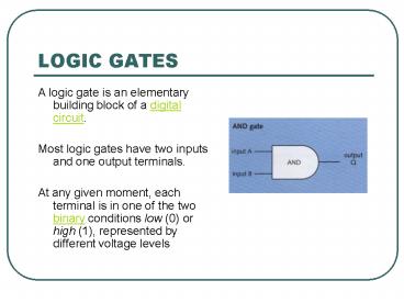
- A logic gate is an elementary building block of a
digital circuit. - Most logic gates have two inputs and one output
terminals. - At any given moment, each terminal is in one of
the two binary conditions low (0) or high (1),
represented by different voltage levels
2
AND, OR and NOT gates
- There are three main types of logic gate
- AND
- NOT
- OR.
3
Two additional types
- In year 11 you also need to know about
- NAND which is an AND a NOT
- NOR which is an OR a NOT
4
Logic gates
- Logic gates are at the heart of digital
electronics - Video recorders, security lamps, alarm systems,
and washing machines are just some of the things
controlled by electronic switches called logic
gates - A logic gate contains a circuit with transistor
switches, but you do not need to know anything
about the circuit inside - All you need to know is how the logic gate will
respond when it gets a signal that is, what
will its output be.
5
Web sites (copy to a word document to link to)
- http//www.kpsec.freeuk.com/seriespa.htmswitchess
eries - http//isweb.redwoods.cc.ca.us/INSTRUCT/Calderwood
D/diglogic/and.htm - http//en.wikipedia.org/wiki/Logic_gateAND_gates
- http//isweb.redwoods.cc.ca.us/INSTRUCT/Calderwood
D/diglogic/index.htm - http//www.bbc.co.uk/schools/gcsebitesize/design/e
lectronics/controllogicrev2.shtml
6
1. Switches in Series
The ideas behind logic gates
- If two on-off switches are connected in series
they must all be closed (on) to complete the
circuit and light the lamp.
7
- if either A or B is OFF (open), the bulb is off
- We say the output of the gate is 0
- If both A and B are ON (closed), the output is 1
8
The AND gate symbol
9
One input (1 and 0) no output so lamp is off
(0) (in the diagram, red means a signal)
10
Two inputs (1 and 1) lamp is lit (output 1)
11
The truth table gives the results of all the
possible switch settings. It uses two logic
numbers 0 for OFF and 1 for ON
Input A Input B Output Q
0 0 0
0 1 0
1 0 0
1 1 1
12
The OR gate
- If two switches are connected in parallel then
only one needs to be closed (on) to complete the
circuit.
13
(No Transcript)
14
One input there is an output so the lamp is on
15
the other input is on, so there is an output
16
Two inputs the lamp is on
17
No input so no output and the lamp is off
18
Truth table for the OR gate
Input A Input B Output Q
0 0 0
0 1 1
1 0 1
1 1 1
19
The NOT gate
- This is also called an INVERTER, because whatever
signal you put in, you get the opposite signal
out. - signals mean a voltage, such as
- 5v to mean 1 (on)
- no voltage to mean 0 (off)
20
The NOT gate
21
No input, but there is an output
22
An input, but there is no output
23
Combining gates An inverter used to reverse a
an output from a gate
24
The AND gate is giving an output, but the
inverter is not
25
Nothing from the AND gate, yet the inverter gives
a signal
26
A new truth table for this would be
- A B C Q
- 0 0 0 1
- 0 1 1 0
- 1 0 1 0
- 1 1 1 0
27
Tape recorder logic gate
- The following diagram shows one use for a logic
gate. - The cassette recorder will only start recording
if the record and play buttons are pressed
together.
28
Alarm system
- The next diagram shows how sensors and logic
gates can be used to control a security lamp. - The sensors and gates have been connected so that
if it is dark and someone approaches, the lamp
comes on automatically. - The last gate cannot provide enough power for the
lamp, so it switches on a relay instead. This
switches on a separate circuit with the lamp in
it.
29
Logic gates working together to make an alarm
system
30
Checking the logic
- To check that the combination behaves as
intended, you can write a truth table for it. - In this case, the light sensors output is LOW
(0) in the dark - the body heat sensors output is HIGH (1) if
someone approaches - the final output Q must be HIGH for the lamp to
come on.
31
- Using combinations of logic gates, complex
operations can be performed. - In theory, there is no limit to the number of
gates that can be arrayed together in a single
device.
32
Two tasks for you to do
- Design a block diagram for a bank safe that needs
two keys to activate the lock. The key sensors
will send an output when the correct key is used.
- Design a logic system for street lights that come
on when it gets dark but only if there are cars
on the road. - For each one, write the truth table
33
- Arrays of logic gates are found in digital
integrated circuits (ICs) used in computers and
all sorts of electronic devices - As technology advances, the required physical
volume for each individual logic gate decreases
and digital devices become capable of performing
ever-more-complicated operations at
ever-increasing speeds.
34
Sensorsthe input devices for logic gates
- The role of sensors in control
- Sensors are used to measure physical quantities
such as temperature, light, pressure, sound, and
humidity. They send signals to the processor. For
example - A security alarm system may have an infra-red
sensor which sends a signal when the beam is
broken. - A heat sensitive sensor in the corner of a room
may detect the presence of a person. - Temperature sensors could be used to control the
heating in a large building. - Pressure sensors in the road could detect
traffic.
35
(No Transcript)
36
Project task for this unit
- Using the web sites and other sources, find out
more about sensors and logic gates. - Compile the information into a brief by useful
report. Direct downloads of material is not
accepted. The report must show that you have
organised the information and presented is as a
report.
Recommended
