
Wide-band Air Fuel Sensor PowerPoint PPT Presentation
1 / 27
Title: Wide-band Air Fuel Sensor
1
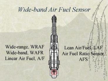
Wide-band Air Fuel Sensor
- Wide-range, WRAF Wide-band, WAFR
- Linear Air Fuel, A/F
Lean Air/Fuel, LAF Air Fuel Ratio Sensor, AFS
2
Wide-Band Oxygen Sensor
- allows engines to operate as
- Lean as 231 (401)
- Rich as 101
- While maintaining closed-loop operation.
- more accurately reflects the oxygen content in
the exhaust vs a conventional oxygen sensor.
3
Comparison of signals
- Regular O2 sensor only measures in a narrow band
at 14.71 - Worthless for low emission vehicles!
- Wideband has a much wider band to measure from
101 to 201 - Necessary for the new direct injection fuel
systems - Necessary for clean air!
4
Operation
Amperage flows here!
Oxygen causes the Nernst cell to generate a
voltage just like an ordinary O2. The oxygen
PUMP Cell compares the change in voltage to the
control voltage from the PCM, balances to
maintain an internal oxygen balance. CURRENT
FLOW is altered creating a positive or negative
current signal that indicates the exact air/fuel
ratio of the engine. The current flow isn't much,
usually only about 0.020 amps or less. PCM
converts the current output into a voltage signal
to be read on a scan tool.
5
Comparison of signals
- Regular o2 outputs voltage
- WRAF outputs CURRENT
6
Operation
The volume ratio at 1 bar air-pressure would be
about 4500 liter air for 1 lb of fuel. 1 bar is
14.5 psi.
7
Current Flows! to maintain voltage!
Voltage created by PCM for the scan tool!
an oxygen pump pulls oxygen from the exhaust into
a diffusion gap to maintain a constant
Voltage. Creating AMPERAGE! .020 amps
8
Amperage!
When the air-fuel ratio is lean, the sensor
produces a positive current ranges from zero to
2.0 milliamperes as the mixture gets leaner up to
221, or leaner. (2.2 bar is 31.91) Testing a
wide-band oxygen sensor usually involves using a
scan tool.
Neat Russian Graphics!
9
Number of Wires
- Lean Air-Fuel Ratio Sensors
- May uses 4, 5, 6, or 7 wires.
- Power wire
- 1 or 2 wires for the electric heater (power
ground) - 3 or 4 sensor wires
Current
10
LAF Conversions - OBDII Scanners
Normalized OBDII Voltage is the data the PCM will
show the scan tool - It is not an actual
measurement
- Most PCMs display the rich and lean status of the
exhaust, - BE CAREFUL! many show the operation of the oxygen
sensor in millivolts from zero to 1000 just as if
the sensor were a conventional zirconia oxygen
sensor. But it is not the actual sensor data.
11
Hondas
- Looks like regular O2
- 5 wires or 6
- Dual Nernst Cell
- 1200F operation temp
- Recommends scan tool for diagnosis
12
Toyota A/FS -Linear A/F 4 Wire
- 1996 appearance
- Looks like regular O2
- 4 wires
- Single Nernst Cell
- 1200F operation temp
- Recommends scan tool for diagnosis
13
Linear A/F signals
- Heater pulse width
- Voltage reference signals 3.3v 3.0v
- Lambda value compared to rich lean
- Substituted HO2S values - slow minimal movement.
14
ToyotaTesting
- a. Disconnect the A/F sensor connector.
- b. measure the resistance between terminals B
and HT. - Resistance 0.8 - 1.4 ohms at 20C (68F).
- 2007 FJ 1.8 - 3.4 ohms
- If the resistance is not as specified, replace
the sensor. - Torque 44 Nm (440 kgf.cm, 31 ft.lbf)
- c. Reconnect the A/F sensor connector.
15
Toyotas sensor output is not a changing analog
voltage, but rather a small (lt 0.020 amps)
bi-directional current.
RICH Positive Amperage
LEAN Negative Amperage
- RICH exhaust produced a positive 4.89 milliamps a
- LEAN exhaust produced a negative 1.53 milliamps.
- The sensor has two signal lines. One line has 3.3
volts, and the other has 3.0 volts on it
(relative to engine ground). - These two voltages do not change.
- Voltage (300 millivolts) across the sensors two
signal lines does not change.
16
Toyotas Intelligent Tester
- A/F CONTROL Change injection volume
- Lower 12.5 or
- increase by 25
- test at less than 3,000 rpm
- A/F CONTROL enables checking and graphing of
A/F - (Air Fuel Ratio) sensor and Heated Oxygen (HO2)
sensorvoltage outputs - To conduct test, select following menu items
- ACTIVE TEST / A/F CONTROL / USER DATA /
- AFS B1S1 and O2S B1S2,and press YES and ENTER
17
Verify Proper Operation - Toyota A/FS
18
Bosch Air Fuel Sensor
- Porsche says all 2010 models will be equipped
with the new sensor! - Diagnose with Factory scan tool.
- Compare lambda values on scan tool and emissions
machine - Watch valuse
- Create RICH
- Create LEAN
19
Testing a Bosch compare Lambda
the Best way to diagnose this A/F ratio sensor
Scan tool Gas Analyzer, Lambda
values should should match, if not more
diagnostics will be required.
20
Testing a Bosch
Heater Circuit pattern
- Check Heater Circuit for Current or Voltage
- Disconnect harness, check resistance of the
trimming resistor, located on Input and Output
pump current wires. - Bosch spec is 30 - 300 ohms.
- Reconnect harness , use DVOM check reference
ground, - Bosch spec is 2.4 - 2.7 volts (refer to actual
specs)
21
Testing a Bosch
- 4. Scope the pump cell Nernst signal
- use sensor reference ground that you just
checked. - Set scope to AC-coupled mode to see negative
swings - Nernst voltage signal remains at .45 volts at all
times - Pump cell voltage should vary about .5 to .6
volts switching across 0 volts - Drive fuel mix rich then lean expect change in
voltage of greater than 1.0 volts.
22
Verify Proper Operation - Bosch LSU 4
Current pump sensor 60 seconds of road test
after replacement shows proper operation Check
Mode 6 Data
Pump cell pumps oxygen ions from one side of the
sensor to the other. PCM monitors the Nernst
signal attempting to keep the voltage at .45
volts. PCM will increase and decrease the
current flow to the pump cell to maintain that
voltage level.
23
Nissan Maxima 2004
24
Infiniti 2008 EX35
25
Tech Tips
- TECH TIPS
- Honda 5-wire "Lean Air Fuel" (LAF) sensors, the
8-pin connector pin for the sensor contains a
special "calibration" resistor. The value of the
resistor can be determined by measuring between
terminals 3 and 4 with an ohmmeter, and will be
2.4K ohms, 10K ohms or 15k ohms depending on the
application. If the connector is damaged and must
be replaced, the replacement must have the same
value as the original. The reference voltage from
the PCM to the sensor on these engines is 2.7
volts. - Saturn also uses a special trim resistor in the
WRAF sensor connector (pins 1 6). The resistor
is typically 30 to 300 ohms. The PCM supplied
reference voltage is 2.4 to 2.6 volts. - If a WRAF sensor has failed because of coolant
contamination, do not replace the sensor until
the leak has been repaired. The new sensor will
fail otherwise. - Some early vehicle systems caused a "simulated"
voltage to be displayed on a scan tool. The
actual value was divided by 5 to comply with
early OBD II regulations. Those regulations have
since been revised, but be aware if you get a
"funky" display on your scan tool
26
Tech tips continued
- variable current signal that can travel in one of
two directions (positive or negative). The signal
gradually increases in the positive direction
when the air/fuel mixture becomes leaner. At the
"stoichiometric" point when the air/fuel mixture
is perfectly balanced (14.7 to 1), the current
flow stops and there is no current flow in either
direction. And when the air/fuel ratio becomes
progressively richer, the current reverses course
and flows in the negative direction. - The PCM sends a control reference voltage
(typically 3.3 volts on Toyota applications, 2.6
volts on Bosch and GM sensors) to the WRAF sensor
through one pair of wires, and monitors the
sensor's output current through a second set of
wires. The sensor's output signal is then
processed by the PCM, and can be read on a scan
tool as the air/fuel ratio, a fuel trim value
and/or a voltage value depending on the
application and the display capabilities of the
scan tool. - For applications that display a voltage value,
anything less than the reference voltage indicate
a rich air/fuel ratio while voltages above the
reference voltage indicates a lean air/fuel
ratio. On some of the early Toyota OBD II
applications, the PCM converts the WRAF sensor
voltage to look like that of an ordinary oxygen
sensor (this was done to comply with the display
requirements of early OBD II regulations).
27
References
- Supersniffers Why Air/Fuel Ration Sensors
- Bob Pattengale, MOTOR.com Dec. 2005
- FJ Cruiser Service Manual, 2007, section ES-313
- ATTS Training, Import Computers, 2008
- Sam Bell, Ralph Birnbaum G Jerry Truglia
- Advanced Engine Performance Diagnostics,
- Halderman, 4th ed. 2009.
- Alflash.com.ua photos by al tech page
- Toyota Wide Range AirFuel Sensor,
- John Thornton, Underhood Service, January 2002
Recommended
