
Shaping 3-D Biodegradable Scaffolds for Tissue Engineering PowerPoint PPT Presentation
Title: Shaping 3-D Biodegradable Scaffolds for Tissue Engineering
1
Shaping 3-D Biodegradable Scaffolds for Tissue
Engineering
Jeffrey M. Karp, Kathy Rzeszutek, and John E.
Davies
Institute for Biomaterials and Biomedical
Engineering, University of Toronto
Overview Shaping tissue engineering scaffolds is
of great importance for in vivo applications to
fit specific defects, and for in vitro
applications where consistent and reproducible
samples must be used to perform controlled
experiments. One method to manufacture scaffolds
of a desired shape involves the use of individual
molds. However, the porosity at the outer margins
of the created scaffolds, which are in contact
with the mold surface, is often compromised by
the creation of an area with significantly
reduced porosity or a polymer skin 1,2
(Figure 1A). Many biodegradable polymeric
scaffolds are soft and delicate. Perhaps for this
reason, methods for reproducibly cutting these
scaffolds, in a manner which retains the original
scaffold porosity and geometry to the margins of
the material, have not yet been explicitly
described. We have created a simple proprietary
system that can be used to quickly and accurately
cut cylindrical shapes from delicate polymeric
scaffold materials that maintain their
morphological features to the margins of the
shapes produced. This technology is of
particular benefit for reproducibly shaping soft
macroporous scaffolds and creating channels in
such scaffolds.
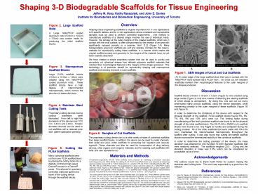
Figure 2. Large Scaffold Mold
A Large TeflonFEP coated aluminum mold
(10.0cm x 10.0cm x 3.0cm) was custom made for
producing the initial scaffold blocks.
Figure 3. Macroporous Scaffold Blocks
Large PLGA scaffold blocks (10.0cm x
10.0cm x 1.2cm) were created using the TeflonFEP
coated aluminum mold. These scaffold blocks have
a high degree of interconnected macroporosity,
which mimics the structure of trabecular bone.
A
B
Figure 1. SEM Images of Uncut and Cut
Scaffolds (A) An outer edge of the large scaffold
block that was in contact with the TeflonFEP
mold surface has a PLGA skin. (B) Once cut,
the resultant scaffolds maintain their
morphological features to the outer margins of
the shapes produced.
Discussion Scaffold blocks (10.0cm x 10.0cm x
1.2cm) (Figure 3) were created using large molds
(Figure 2) only as a means of obtaining the
starting scaffolds of which shape is unimportant.
By doing this, one can cut out many small-sized
highly porous scaffolds, using the device
described, while maintaining porosity to the
outer margins of these scaffolds (Figure 1B and
Figure 6). In order to determine the limitations
of the device with respect to the physical
strength of the scaffold, PLGA scaffold blocks
having 5, 6, 7, 8, 9 and 10 (w/v) were cut.
The limiting factor during manufacturing of the
final cylindrical scaffold was found to be the
physical strength of the initial scaffold block.
The 5 PLGA in DMSO (w/v) scaffold blocks were
found to be very fragile to handle and collapsed
during the cutting process. All of the other
scaffolds that were made with 6-10 (w/v)
maintained the interconnected macroporosity
throughout the scaffold after cutting. It was
also found that cutting pre-wetted scaffold
blocks improved the dimensional stability of the
cylindrical scaffolds. In order to determine the
cutting precision of the device, the mass
deviation was obtained for one hundred 10.0mm
diameter scaffolds that were randomly selected.
The scaffolds weighed 23.0 3.0mg and the
standard deviation in mass was 5.3, which can be
considered an acceptable value of
error. Acknowledgements The authors would like to
thank Keith Porter for custom making the
stainless steel cutting tools. This work was
supported by a grant from the ORDCF.
Figure 4. Stainless Steel Cutting Tools
Proprietary cutting devices having
various diameters were fabricated. From left to
right the diameters of the devices are 10.0 mm,
4.4mm and 2.4mm. Smaller diameter devices can be
used to cut scaffolds with a reduced pore size.
(patent application pending)
Figure 6. Samples of Cut Scaffolds The
proprietary cutting device can cut a wide variety
of sizes of cylindrical scaffolds from larger
scaffold blocks. In addition, the device can be
used to create channels, both radial and axial,
within scaffolds for promoting cell migration and
vascular ingrowth. These channels can also be
used for incorporation of drug delivery devices,
other organic and inorganic materials, and for
seeding such scaffolds with cells. (the ruler
represents cm)
Figure 5. Cutting the PLGA Scaffolds Many
cylindrical scaffolds were cut from one PLGA
scaffold block by placing the cutting tools into
a digitally controlled high speed Dremel housed
in a Dremel press. This allowed for precisely
controlled rotational speed and travel of the
cutting device
Materials and Methods Poly(lactide-co-glycolide)
(PLGA) 75/25 scaffolds were produced by modifying
a previously described technology Holy et al
1997. Briefly, the starting PLGA 7525 3-D
scaffold blocks were prepared by dispersing
glucose crystals having 0.85 to 1.18mm dimensions
in a solution of PLGA 7525 in dimethysulfoxide
(5, 6, 7, 8, 9 and 10 PLGA (w/v)). The
sugar/polymer mixture was then placed in a
TeflonFEP coated aluminum mold (Figure 2) and
allowed to set. When the polymer precipitated,
the glucose crystals were extracted from the
polymer, which resulted in a 3-D scaffold block
having macroporous interconnected porosity. The
dimensions of the resultant scaffold were 10.0cm
x 10.0cm x 1.2cm (Figure 3). The cutting device
was turned on a lathe from a stainless steel (316
grade) rod. Three different cylinder sizes 10.0
mm, 4.4 mm, and 2.4 mm in diameter were
manufactured (Figure 4). One end of the cylinder
was used to create the cutting edge, while the
other end was reduced in diameter to 1/5 in or
1/8 in to fit either a standard drill or Dremel
(Model 398) respectively. A Multipro Deluxe drill
press stand Model 212 type II was used with the
Dremel for enhanced control and precision
(Figure 5). The cylindrical scaffolds were cut to
the desired length using a custom-made Teflon
guiding device and a standard double-edged razor
blade. The cutting devices were ultrasonically
cleaned with acetone and Decon, and then rinsed
with double distilled water and ethanol ( 70 and
100) prior to use.
References 1. Holy CE, Davies JE, Shoichet MS.
In Biomaterials, Carriers For Drug Delivery, And
Scaffolds For Tissue Engineering (Peppas, N.A.,
Mooney, D.J., Mikos, A.G., Brannon-Peppas, L.,
Eds.) AiChE Press, NY, 1997 272-274. 2.
Agrawal CM, Ray RB. Biodegradable polymeric
scaffolds for musculoskeletal tissue engineering.
J Biomed Mater Res 200155(2)141-50. 3. Mikos
AG, Temenoff JS. Formation of highly porous
biodegradable scaffolds for tissue engineering.
EJB Electronic J Biotech 20003(2).
through the scaffold blocks.
Recommended
