
Further with interferometry - PowerPoint PPT Presentation
1 / 28
Title: Further with interferometry
1
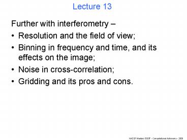
Lecture 13
- Further with interferometry
- Resolution and the field of view
- Binning in frequency and time, and its effects on
the image - Noise in cross-correlation
- Gridding and its pros and cons.
2
Earth-rotation synthesis
Apply appropriate delays like measuring V with
virtual antennas in a plane normal to the
direction of the phase centre.
3
Earth-rotation synthesis
Apply appropriate delays like measuring V with
virtual antennas in a plane normal to the
direction of the phase centre.
4
Earth-rotation synthesis
Apply appropriate delays like measuring V with
virtual antennas in a plane normal to the
direction of the phase centre.
5
Field of view and resolution.
Single dish FOV and resolution are the same.
FOV ?/d (d dish diameter)
Resolution ?/d
6
Field of view and resolution.
Aperture synthesis array FOV is much larger than
resolution.
d
FOV ?/d
Resolution ?/D (D longest baseline)
D
7
Field of view and resolution.
Phased array Signals delayed then added. FOV
again resolution.
Good for spectroscopy, VLBI.
d
FOV ?/D
Resolution ?/D
D
8
LOFAR can see the whole sky at once.
9
Reconstructing the image.
- The basic relation of aperture synthesis
- where all the (l,m) functions have been bundled
into I. We can easily recover the true
brightness distribution from this. - The inverse relationship is
- But, we have seen, we dont know V everywhere.
10
Sampling function and dirty image
- Instead, we have samples of V. Ie V is multiplied
by a sampling function S. - Since the FT of a product is a convolution,
- where the dirty beam B is the FT of the
sampling function - ID is called the dirty image.
11
Painting in V as the Earth rotates
12
Painting in V as the Earth rotates
13
But we must bin up in ? and t.
This smears out the finer ripples. Fourier theory
says finer ripples come from distant
sources. Therefore want small ??, ?t for
wide-field imaging. But ? huge files.
14
We further pretend that these samples are points.
15
Whats the noise in these measurements?
- Theory of noise in a cross-correlation is a
little involved... but if we assume the source
flux S is weak compared to skysystem noise, then - If antennas the same,
- Root 2 smaller SNR from single-dish of combined
area (lecture 9). - Because autocorrelations not done ? information
lost.
16
Resulting noise in the image
Spatially uniform but not white.
(Note noise in real and imaginary parts of the
visibility is uncorrelated.)
17
Transforming to the image plane
- Can calculate the FT directly, by summing sine
and cosine terms. - Computationally expensive - particularly with
lots of samples. - MeerKAT a days observing will generate about
8079170005005.4e10 samples. - FFT
- quicker, but requires data to be on a regular
grid.
18
How to regrid the samples?
Could simply add samples in each box.
19
But this can be expressed as a convolution.
Samples convolved with a square box.
20
Convolution ? gridding.
- Square box convolver is
- Gives
- But the benefit of this formulation is that we
are not restricted to a square box convolver. - Reasons for selecting the convolver carefully
will be presented shortly.
21
What does this do to the image?
- Fourier theory
- Convolution ? Multiplication.
- Sampling onto a grid ? aliasing.
22
A 1-dimensional example dirty image ID
V ? I via direct FT
23
A 1-dimensional example dirty image ID
Multiplied by the FT of the convolver
24
A 1-dimensional example
The aliased result is in green
Image boundaries become cyclic.
25
A 1-dimensional example
Finally, dividing by the FT of the convolver
26
Effect on image noise
Direct FT
Gridded then FFT
27
Aliasing of sources none in DT
This is a direct transform. The green box
indicates the limits of a gridded image.
28
Aliasing of sources FFT suffers from this.
The far 2 sources are now wrapped or
aliased into the field and imperfectly
suppressed by the gridding convolver.
Recommended
CrystalGraphics Presentations


