
Minnesota Department of Natural Resources PowerPoint PPT Presentation
Title: Minnesota Department of Natural Resources
1
Minnesota Department of Natural Resources ArcView
Utilities Extension Users Guide
Introduction
This document describes the functionality and use
of the ArcView Utilities extension for the
ArcView desktop GIS software. These tools were
developed out of the need for additional
geoprocessing functionality within ArcView by
resource managers. The ArcView Utilities
extension contains a number of extended GIS
functions that are commonly used by resource
managers but not available on the standard
ArcView interface. The remainder of this document
will describe the available tools and will use
examples to illustrate what they do and how they
work.
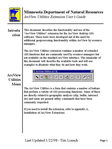
ArcView Utilities Menu
The ArcView Utilities is a form that contains a
number of buttons that perform a variety of GIS
processing functions. Some of these are directly
related to geographic analysis (clip, buffer,
intersect etc) and some are general utility
commands that have been commonly requested. If
you need to install the extension, refer to
appendix A, Installation of ArcView Extensions.
Last Updated 1/22/98 - Tim Loesch
2
Minnesota Department of Natural Resources ArcView
Utilities Extension Users Guide
Accessing Extensions
To access the utilities form within ArcView you
can use the FILE Extensions option when the
project window is active.
Loading the Utilities Extension
Once selected you will see the Extensions Dialog
window that shows the extensions that are
available to ArcView. Scrolldown until you see
ArcView Utilities-DD and click on the check box
adjacent to it. Then press the OK button.
3
Minnesota Department of Natural Resources ArcView
Utilities Extension Users Guide
ArcView Utilities Form
The ArcView Utilities form will then appear. The
form consists of nine buttons. Each button
operates on one or more themes to produce a new
output theme (in most cases). This is a
modeless form, that is, it can be moved around
the screen and used when needed. Other menus,
buttons and tools on the interface are fully
accessible when this form is open. To use a
button on the Utilities form, simply press it
with the mouse pointer. Thats it. Depending on
the function of the button you will be prompted
for additional information. As you move the
mouse pointer over the buttons on the form a
message will appear in the status bar of the
ArcView interface (at the bottom of the ArcView
window). If you hold the mouse pointer on a
button momentarily, a bubble with text will
appear that shows a short description of the
buttons functionality. NOTE The bubble text
capability is only available with Windows 95 or
Windows NT. For Windows 3.x or UNIX machines
refer to the bottom of the ArcView window for
help.
What do the Icons Mean?
4
Minnesota Department of Natural Resources ArcView
Utilities Extension Users Guide
!
To close the form just press the X button in the
upper right hand portion of the forms banner.
This does not unload the extension, it simply
closes the form and frees up display space on
your monitor. Once the form has been closed it
can be re-opened, as long as the extension is
loaded, using the WINDOW Show ArcView Tools
option. This will re-open the form and make the
commands accessible to you.
Closing the Utilities Form
Re-Opening the Utilities Form
Unloading the Utilities Extension
To unload the ArcView Utilities extension you
must access the Extensions dialog through the
FILE Extensions option and un-checking the box
next to the ArcView Utility Tools extension
selection. This will remove the form, and menu
options related to it, from the current ArcView
session.
5
Minnesota Department of Natural Resources ArcView
Utilities Extension Users Guide TABLE OF CONTENTS
CLIP - Page 7
BUFFER Page 13
INTERSECT - Page 19
MERGE - Page 25
ERASE - Page 29
UNION - Page 33
SUBSET LEGEND - Page 39
CALCULATE AREA, PERIMETER LENGTH - Page 43
SHIFT COORDINATES - Page 45
MULTI-POINT TO POINT - Page 51
UNGROUP POLYGONS - Page 55
Appendix A - Installation of ArcView Extensions -
Page 59
6
This page intentionally left blank.
7
Minnesota Department of Natural Resources ArcView
Utilities Extension Users Guide
The CLIP Button is used to extract subsets of
information from existing geographic data sets.
This is equivalent to taking a spatial cookie
cutter to some geographic dough. You take the
outline of something, a watershed, city or county
for example, and press it into the dough. In this
case the dough is a geographic data set.
Clipping is useful when you want to perform an
analysis on a specific area. Think about how
people work. A wildlife manager may be developing
a management plan for an existing wildlife
management area or a planner may be working on a
county plan. They dont need data for the
remainder of the state to do the task at
hand. By clipping geographic databases you can
reduce the amount of information your computer
has to load into memory when you access the data.
The reduction in data volume will speed up your
computer by freeing memory resources and will
maximize disk space. The clipping process
requires two or more themes as input. The
Clipping Theme is a polygon theme where a
polygon, or set of polygons, defines the outline
of the area to be Clipped. This theme is the
geographic cookie cutter. The Themes to be
Clipped are the themes whose data you want to
extract. These themes are your geographic
dough. The themes to be clipped can be
Shapefiles, Coverages or Librarian layers that
contains points, lines or polygons. The Clipping
Theme must be a polygon theme that has one or
more polygons selected. The CLIP process
produces new shapefiles that contains the
features of the Themes to be Clipped that fall
inside the selected polygons of the Clipping
Theme. The theme attribute tables will contain
the fields that were in the Theme to be Clipped
and the Area/Perimeter/Length and acres fields
will be updated based on the new values.
The CLIP Button
Why CLIP?
What do I Need to CLIP?
What does CLIP Produce?
8
Minnesota Department of Natural Resources ArcView
Utilities Extension Users Guide
Lets say that you are working in Crow Wing
county, MN and want to look at the Pre-Settlement
vegetation for the county. You have a file that
shows the Pre-Settlement vegetation for the state
and another shapefile that shows the counties in
Minnesota. What you want is a subset of the
Pre-Settlement vegetation for Crow Wing county.
This is a perfect time for a CLIP. You see the
two maps below, in this case the Pre-Settlement
vegetation is the theme to be clipped (dough) and
the county theme is the clipping theme
(cookie-cutter).
An Example Clip
Pre-Settlement Vegetation Theme to be Clipped
Counties in Minnesota The Clipping Theme
The first step in the clipping process is to
select the polygon that represents Crow Wing
county in the county theme. If you wanted to you
could select more than one county and their
combined outline would be used as the clipping
polygon. You must also make sure that you have
the theme to be clipped on the View document.
Step 1 - Select the Clipping Polygons
9
Minnesota Department of Natural Resources ArcView
Utilities Extension Users Guide
An Example Clip
CLIP Button
Step 2- Press the CLIP Button
Once you have the two themes on the View and the
clipping polygons selected you are ready to
proceed. If the ArcView Utilities form is open
press the CLIP Button. If the form is not open,
use the WINDOW Show ArcView Utility Tools option
to open it.
Step 3- Select the Theme(s) to be Clipped
Once the CLIP command is selected the CLIP Themes
form will appear. This form is made up of a list
of themes to clip to the left and a dropdown box
that shows the polygon themes in the View that
are available for use as clipping themes. While
you could select several themes in this list, in
this case we are only interested in clipping the
Pre-Settlement Vegetation theme.
10
Minnesota Department of Natural Resources ArcView
Utilities Extension Users Guide
An Example Clip
Step 4- Select the Clipping Theme
Then specify the clipping theme by selecting the
appropriate theme from the drop-down list of
polygon themes in the right hand side of
the form. Remember that one or more polygons in
this theme must be selected. If not, you will get
the following error message.
Step 5- Retain or Change Filenames
AT this point the program is ready to go out and
clip the theme or themes that you specified. At
this time the program needs to know where you
want to store the new files and how you want the
filenames to be handled. There are two options,
retain the current filename or change the
filenames to something else. This is indicated
bye the Change Filenames checkbox on the CLIP
Themes form. By default, this check-box is not
selected so the original name of the file will be
retained. If you change the filenames you will be
required to enter a new filename for the output
shapefile. If not, you will simply need to
specify an output location. In most cases it is
desirable to retain the original filename. When
you are finished entering the paramters on the
Form press the OK button to proceed.
11
Minnesota Department of Natural Resources ArcView
Utilities Extension Users Guide
An Example Clip
If the program finds any files in the output
location that are in danger of being overwritten
you will be prompted to see if thats what you
really want to do. If so, press OK and the
process will proceed.
CLIP Results
What you see above is the resulting shapefile
that was produced from the CLIP procedure. As you
can see, just the part of the Pre-Settlement
Vegetation coverage that occupied the outline of
Crow Wing county was copied into the output
shapefile.
12
This page intentionally left blank.
13
Minnesota Department of Natural Resources ArcView
Utilities Extension Users Guide
The Buffer Button is used to create a buffer
around the selected objects within a geographic
data set. The distance of the buffer is defined
by the user. Buffering is useful when you want
to identify features that exist within a certain
distance of features of interest. You can then
use the output buffered shapefile as a Clip Theme
in the CLIP command. This would leave you with a
file that contained only those features within
the buffer zone. The buffer process requires one
theme as input. The theme to be buffered can be
a Shapefile, Coverage or Librarian layer that
contains points, lines or polygons and one or
more of these features must be selected. Buffer
distances are entered based on the Map or
Distance units specified in the View Property
Sheet. Distance units are used first. If they are
not specified then the Map units property is used
as an input measure. Negative values for buffers
are allowed on polygon features only. In this
case, a buffer on the inside of the polygon will
be created rather than a buffer outside of the
polygon. The Buffer process generates a new
shapefile that contains polygons that represent
the boundaries of the buffered area. The output
theme attribute table will contain two fields,
SHAPE and INSIDE. The Shape field is defined by
ArcView and the INSIDE field value of 1
represents a polygon that is inside the buffer
area while a value of 100 represents polygons
formed that are outside the buffer area. All
polygons generated are considered a single
entity. If you wish to separate these polygons
use the UNGROUP Button. If you wish to add the
AREA, PERIMETER and ACREs fields, use the UPDATE
AREA/PERIMETER/LENGTH button.
The BUFFER Button
Why Buffer?
What do I Need to Buffer?
How are Buffer Distances Entered?
What Does Buffer Produce?
14
Minnesota Department of Natural Resources ArcView
Utilities Extension Users Guide
An Example Buffer
Lets say that you have a number of Eagles nests
inventoried and stored as point locations in an
ArcView shapefile. What you want to do is create
a new file that shows a buffer zone around the
eagles nests of 1/4 mile or 1320. This data set
has been added to a View and is named Eagles
Nests. Below is a picture of the Eagles Nests
with a river feature added to the display for
visual context.
Step 1 - Select the Features to be Buffered
The first step in the buffering process is to
select the features that you want to buffer.
Using the Selection tool, select the features of
interest. In this case well select all of the
eagles nests in the file. Remember to have the
theme of interest active and then use the feature
selection tool to select the features. Once you
have selected features they will be highlighted
in the current selection color (usually yellow).
15
Minnesota Department of Natural Resources ArcView
Utilities Extension Users Guide
An Example Buffer
BUFFER Button
Once you have the feature of interest selected
you are ready to buffer. If the ArcView Utilities
form is open, press the BUFFER Button. If the
form is not open, use the WINDOW Show ArcView
Utility Tools option to open it. Remember that
the buffer option relies on the value of the Map
Units in the Views Property sheet. If the Map
Units have not been set, you will see the
following message
Step 2 - Press the BUFFER Button
You will need to edit the property sheet of the
View before you can continue. Use the VIEW
Properties option to define the Map units
property. If you do not have any features
selected you will get the following message
16
Minnesota Department of Natural Resources ArcView
Utilities Extension Users Guide
An Example Buffer
Now you are ready to define the Buffer size.
Enter the size of the buffer in the units that
are defined in the dialog. In the above example,
the Distance units of the View is Miles,
therefore the dialog requests the buffer distance
in miles. We want a 1/4 mile buffer so the
appropriate entry is 0.25. You will then be
asked to enter a new filename and location. The
default shapefile name is BUFFER.SHP. You can
change this as you like. Once entered the Buffer
command will commence and a buffered theme added
to the View. The picture below shows the results
of this operation. The green polygons represent
the buffer polygons.
Step 3 - Enter the Buffer Distance
Step 4 - Enter a New Filename
17
Minnesota Department of Natural Resources ArcView
Utilities Extension Users Guide
An Example Buffer
Buffer Notes
If you look at the above graphic of the theme
attribute table for the buffered Eagles nests
you will see that there is only one record. This
record represents all of the polygons that were
created. If you select one, all are selected. If
you want to split these into individual polygons
that each have a record in the theme attribute
table use the Ungroup Polygons button on the
ArcView Utilities form. The result will be the
table below
Ungroup Button
18
This page intentionally left blank.
19
Minnesota Department of Natural Resources ArcView
Utilities Extension Users Guide
The INTERSECT Button
The INTERSECT Button is used to perform a spatial
overlay of two themes to determine the spatial
coincidence of the features in the
themes. Intersection is useful when you want to
look at one mapped variable in relation to
another mapped variable. A fisheries manager may
want to know what the land cover is in each
watershed in their management area to determine
if there is any relationship between the land
cover types and the water quality of the lakes in
a watershed. The intersect command is the way to
get the job done. The Intersection process
requires two themes as input. An Intersect
Theme which can be a line or polygon theme, and
an Overlay Theme which must be a polygon theme.
In the previous example we want to know what land
cover is in each watershed. In this case our
Intersect theme is the theme that shows the land
cover. The Overlay theme is the theme that
contains the watershed boundaries. The Intersect
Button produces a polygon shapefile where the
polygons or lines represent the combinations of
the two input shapefiles. In the example the
output polygons would be combinations of
watershed and land cover. Thus, each polygon or
line would have fields that identify the
polygons watershed and land cover. An Intersect
is kind of like a Clip but with two main
differences 1) the output file consists of
only the geographic area common to both
themes. Any features outside of the intersection
are not included in the output file
2) The output theme attribute table contains
the fields from both the Intersect
theme and the Overlay theme
Why INTERSECT?
What do I Need to INTERSECT?
What does INTERSECT Produce?
20
Minnesota Department of Natural Resources ArcView
Utilities Extension Users Guide
An Example INTERSECT
Building on the example we did for the CLIP
command lets say we wanted to determine the
distribution of Pre-Settlement Vegetation within
the Watershed Basins in Crow Wing county. You
have a shapefile that shows the Pre-Settlement
Vegetation and one that shows the watershed
basins in Crow Wing County. What you want is a
theme that shows the Intersection of these two
pieces of information. Below are snapshots of
the two themes we will use in this analysis. In
this case the Pre-Settlement Vegetation theme is
the Intersect theme and the Watershed Basin theme
is the Overlay theme.
Pre-Settlement Vegetation The Intersect Theme
Watershed Basins The Overlay Theme
21
Minnesota Department of Natural Resources ArcView
Utilities Extension Users Guide
An Example INTERSECT
INTERSECT Button
Once you have the themes of interest on the View
press the INTERSECT button on the ArcView
Utilities form. If it is not open use the WINDOW
Show ArcView Utility Tools option to open
it. You will then be prompted to select the
Intersect Theme from a list of polygon or line
themes in the currently active View document. In
this case the Pre-Settlement Vegetation theme is
our Intersect Theme.
Step 1 - Press the INTERSECT Button
Step 2 - Select the Intersect Theme
22
Minnesota Department of Natural Resources ArcView
Utilities Extension Users Guide
An Example INTERSECT
Now you will be prompted to enter the Overlay
theme from a list of the Polygon themes in the
currently active View. In this case our Overlay
theme is the Watershed Basins theme.
Step 3 - Select the Overlay Theme
You will be requested for a new filename. The
default filename is INTER.SHP. You can specify a
new location and theme name if you wish. Once you
enter a filename the two themes will be
intersected and you will be prompted to add the
new theme to a view.
Step 4 - Enter a New Filename
23
Minnesota Department of Natural Resources ArcView
Utilities Extension Users Guide
An Example INTERSECT
INTERSECT Results
The snapshot above shows the resulting output. As
you can see, there are lines that cross
vegetation types. These are watershed boundaries.
Below is part of the table where you can see that
both the vegetation and watershed are part of the
theme attribute table.
24
This page intentionally left blank.
25
Minnesota Department of Natural Resources ArcView
Utilities Extension Users Guide
The MERGE Button
The MERGE button allows the user to merge
(append) physically separate shapefiles, of the
same theme but different areas, into a single
shapefile. In conventional terms this is
equivalent to taking two quad maps, trimming the
edges with a scissors, aligning the two map
sheets and taping them together, except that its
done in the computer and the maps, scissors and
tape you are using are silicon based. Merging
themes is useful when you have a theme that is
organized geographically (by county or quad for
example), and you need to analyze two or more
geographic units (tiles). If you wanted to look
at the wetlands for two adjacent counties you
might want to join them together so that
statistics are easier to create. Another common
reason for merging shapefiles is when you have
many tiles you want to examine. By merging the
files together you only have to deal with one
theme instead of one theme for every tile. Merge
requires that you have two or more themes in a
View that cover different areas and represent the
same data layer. That is, you could merge two
adjacent townships of forest inventory data but
you could not merge a township of soils with an
adjacent township of forestry data. The themes
that you are merging should have the same
attributes and represent different spatial
extents. The MERGE command produces a new
shapefile that contains the contents of the input
files. All tile borders will remain.
Why MERGE?
What do I Need to MERGE?
What does MERGE Produce?
26
Minnesota Department of Natural Resources ArcView
Utilities Extension Users Guide
An Example MERGE
While working on a project you realize that you
need some wetland information. Digging into this
problem you find out that you can get your hands
on some National Wetlands Inventory data that is
stored based on the USGS 124,000 quad tiling
system. Youre working in an area that includes
two 124,000 scale quads, Coon Lake Beach and
Linwood. The data sets are shown below.
Coon Lake Beach Quadrangle
Linwood Quadrangle
You want to be able to calculate accurate areas
and work on these two files and would prefer that
they are a single file for convenience and to
reduce the complexity of your ArcView project .
This is a job for the MERGE command.
27
Minnesota Department of Natural Resources ArcView
Utilities Extension Users Guide
An Example MERGE
MERGE Button
Once you have the themes of interest on the View
press the MERGE button on the ArcView Utilities
form. If it is not open use the WINDOW Show
ArcView Utility Tools option to open it. You
will then be prompted to select the theme to
merge from a list of themes in the View. As you
can MERGE many themes you will be presented with
the prompt many times. In this case we will be
selecting the LINWOOD NWI data to be the first
theme to MERGE.
Step 1 - Press the MERGE Button
Step 2 - Select the Themes to be MERGEd
28
Minnesota Department of Natural Resources ArcView
Utilities Extension Users Guide
An Example MERGE
Step 2 - Select the Themes to be MERGEd
Keep selecting files until you have entered all
desired themes. You will notice that as you
select themes they will be removed from the list.
If you are done selecting themes then press the
Cancel button. Once you have selected the
themes you are interested in and pressed the
Cancel button you will be requested to enter a
new filename. The program will crunch the numbers
and merge the files you are interested in. Once
complete, you will be asked to add the theme to a
view and youre done! The output results are
shown below with the quad boundaries shown for
visual context.
Step 3 - Enter a new Filename
29
Minnesota Department of Natural Resources ArcView
Utilities Extension Users Guide
The ERASE Button
The ERASE button allows the user to erase
features in the input theme based on a set of
polygons in another theme. This is equivalent to
masking out the features in areas that are not
needed for a specific analysis. ERASE is
conceptually opposite of what the CLIP command
performs. In the CLIP command the output features
are those that are inside the polygons of
interest. In ERASE, the output features are those
that are outside the polygons of interest. When
you erase features you are removing features that
fall within the input polygons by clipping them
at the edges. This is important in cases where
you want to consider the area of the features in
one theme but exclude those areas that are in
another theme. For example, if you wanted to
create a map that shows population density per
square mile, you may want to consider those areas
that can support population. You could use the
ERASE command to remove the water features from a
shapefile that contains population information.
After all, you cant build and live on water so
why should be consider it in our population
density calculations? ERASE requires a point,
line or polygon theme (the Input Theme) that
contains the features you want to erase and a
polygon theme (the Erase Theme) that contains the
areas you wish to erase the features in the input
theme. ERASE produces a new shape theme that
contains the features from the Input theme that
are outside of the polygons in the Erase theme.
Why ERASE?
What do I Need to ERASE?
What does ERASE Produce?
30
Minnesota Department of Natural Resources ArcView
Utilities Extension Users Guide
An Example ERASE
Lets say that you wanted to create a population
density map for a particular area and that you
only wanted to consider that area that was upland
(not water or wetlands) in the density
calculations. You have a polygon shapefile that
displays the cities, towns, and townships with
population information in the feature attribute
table and a polygon shapefile that shows wetlands
and water bodies. Using the ERASE command you
can remove the area of the wetlands and water
bodies from the cities and townships shapefile.
By then using the remaining upland area a more
appropriate value of population density can be
calculated.
Cities and Townships (the Input Theme)
Wetlands and Water Bodies (the Erase Theme)
31
Minnesota Department of Natural Resources ArcView
Utilities Extension Users Guide
An Example ERASE
ERASE Button
Start the process by making sure that your themes
of interest are on the View and then press the
ERASE button in the ArcView Utilities Form.
Step 1 - Press the ERASE Button
Step 2 - Select the Input Theme
The next step is to select the theme whose
features you wish to erase. In this case the
Input theme is the theme that contains the City
and Township Polygons.
Step 3 - Select the Erase Theme
Now select the theme that contains the features
you want to use to erase features from the Input
theme. This must be a polygon theme.
32
Minnesota Department of Natural Resources ArcView
Utilities Extension Users Guide
An Example ERASE
You will be then requested to enter a new name
for the output shapefile. Once a name is entered,
press the OK button and the program will proceed
to perform the ERASE. Once the ERASE is complete
the new theme will be added to the View. The
following graphic shows the results of the ERASE
command. As you can see areas within the theme
that were coincident with water features have
been removed.
Step 4 - Specify an Output Filename
33
Minnesota Department of Natural Resources ArcView
Utilities Extension Users Guide
The UNION Button
The union Button is used to perform a spatial
overlay of two themes to determine the spatial
coincidence of the features in the themes. Union
is useful when you want to look at one mapped
variable in relation to another mapped variable.
A fisheries manager may want to know what the
land cover is in each watershed in their
management area to determine if there is any
relationship between the land cover types and the
water quality of the lakes in a watershed. The
union command is the way to get the job
done. The union process requires two themes as
input. A Union Theme which must be a polygon
theme, and an Overlay Theme which must be a
polygon theme. In the previous example we want to
know what land cover is in each watershed. In
this case our union theme is the theme that shows
the land cover. The Overlay theme is the theme
that contains the watershed boundaries. The
Union Button produces a polygon shapefile where
the polygons or lines represent the combinations
of the two input shapefiles. In the example the
output polygons would be combinations of
watershed and land cover. Thus, each polygon or
line would have fields that identify the
polygons watershed and land cover. An Union is
much like an Intersect except that the output
contains all polygons in both files whether they
overlap or not. The output file contains all the
polygons of the two input files.
Why UNION?
What do I Need to UNION?
What does UNION Produce?
34
Minnesota Department of Natural Resources ArcView
Utilities Extension Users Guide
An Example UNION
Building on the example we did for the CLIP
command lets say we wanted to determine the
distribution of Pre-Settlement Vegetation within
the Watershed Basins in Crow Wing county. You
have a shapefile that shows the Pre-Settlement
Vegetation and one that shows the watershed
basins in Crow Wing County. What you want is a
theme that shows the Intersection of these two
pieces of information. Below are snapshots of
the two themes we will use in this analysis. In
this case the Pre-Settlement Vegetation theme is
the Union theme and the Watershed Basin theme is
the Overlay theme.
Pre-Settlement Vegetation The Intersect Theme
Watershed Basins The Overlay Theme
35
Minnesota Department of Natural Resources ArcView
Utilities Extension Users Guide
An Example UNION
UNION Button
Once you have the themes of interest on the View
press the UNION button on the ArcView Utilities
form. If it is not open use the WINDOW Show
ArcView Utility Tools option to open it. You
will then be prompted to select the Union Theme
from a list of polygon themes in the currently
active View document. In this case the
Pre-Settlement Vegetation theme is our Union
Theme.
Step 1 - Press the UNION Button
Step 2 - Select the Union Theme
Now specify which attributes you want to carry
from the Union theme to the output theme. NOTE
The more fields you select, the longer the
process will take.
Step 3 - Select Union Theme Output Fields
36
Minnesota Department of Natural Resources ArcView
Utilities Extension Users Guide
An Example UNION
Now you will be prompted to enter the Overlay
theme from a list of the Polygon themes in the
currently active View. In this case our Overlay
theme is the Watershed Basins theme.
Step 4 - Select the Overlay Theme
Step 5 - Select Overlay Theme Output Fields
Now specify which attributes you want to carry
from the Overlay theme to the output theme. NOTE
The more fields you select, the longer the
process will take.
You will be requested for a new filename. The
default filename is THEME1.SHP. You can specify a
new location and theme name if you wish. Once you
enter a filename the two themes will be Unioned
and you will be prompted to add the new theme to
a view.
Step 6 - Enter a New Filename
37
Minnesota Department of Natural Resources ArcView
Utilities Extension Users Guide
An Example UNION
UNION Results
The snapshot above shows the resulting output. As
you can see, there are lines that cross
vegetation types. These are watershed boundaries.
Below is part of the table where you can see that
both the vegetation and watershed are part of the
theme attribute table.
38
This page intentionally left blank.
39
Minnesota Department of Natural Resources ArcView
Utilities Extension Users Guide
The SUBSET LEGEND Button
The SUBSET LEGEND button is used to reduce a
themes legend classes to those classes that
exist in the current theme. Each class in the
legend is compared to a list of valid values in
the current theme. If the legend class does not
have an associated value in the theme then it
(the legend class) is removed from the themes
legend. Saved legends are an efficient way to
distribute legend information that may be used
over and over. These saved legends, often called,
Global legends typically contain the entire
range of valid values for a particular field in a
data set. Often times, you will be working in a
smaller area that may only contain a subset of
these values. When that happens you have classes
in your legend that dont show up in your map.
This can lead to confusion and difficulty
interpreting the map. To subset a legend you
only need to have a theme with a UNIQUE legend
that may or may not have more classes than you
need. These are often created by Loading a legend
or by using the Theme Catalog utilities. The
SUBSET LEGEND command produces a theme with a
legend that matches the data in the theme. That
is, there are no extra classes in the new theme
legend. This increases the readability of the
legend and makes them easier to interpret.
Why SUBSET a Legend?
What do I Need to SUBSET a LEGEND?
What does SUBSET LEGEND Produce?
40
Minnesota Department of Natural Resources ArcView
Utilities Extension Users Guide
An Example SUBSET LEGEND
Lets assume that you are working on a shapefile
of Ramsey County Pre-Settlement vegetation that
was extracted from a statewide data set. When
the CLIP operation was complete you were left
with a legend that contained all of the possible
landcover classes throughout the state. In fact,
there are18 different landcover classes
throughout the state and only seven in Ramsey
County and you would like the legend to reflect
the contents of the file.
Step 1 - Load a Theme and a Legend
Ramsey County
41
Minnesota Department of Natural Resources ArcView
Utilities Extension Users Guide
An Example SUBSET LEGEND
SUBSET LEGEND Button
Step 2 - Press the SUBSET LEGEND Button
Once you have the theme and legend of interest on
the View press the SUBSET LEGEND button on the
ArcView Utilities form. If it is not open use the
WINDOW Show ArcView Utility Tools option to open
it. The legend of the currently active theme
will be subset. Any classes found in the theme
that are not found in the legend will be assigned
to a unique class as Unknown and given a default
color.
SUBSET LEGEND Results
Ramsey County
42
This page intentionally left blank.
43
Minnesota Department of Natural Resources ArcView
Utilities Extension Users Guide
The UPDATE AREA, PERIMETER and LENGTH Button
The UPDATE AREA, PERIMETER, and LENGTH button
allows the user calculate feature geometry (i.e.
area, length etc) for each feature (lines and
polygons) in a theme. This command works on the
feature attribute table of a theme and then goes
through each features and calculates the
following feature geometry values
Polygons Area - the area of a polygon in native
coordinate units. Perimeter - The perimeter
length of the polygon in native coordinate
units. Acres - the area in acres (assuming the
native coordinates are in UTM meters). PerFeet
- The perimeter length of the polygon in feet
(assuming the native coordinates are in UTM
meters). Lines Length - The length of
a line segment in native coordinate
units. Lfeet - The length of a line segment in
feet (assuming the native coordinates are in UTM
meters). ArcView does not manage any feature
geometry values when features are created or
edited as does Arc/Info. If you are using an
Arc/Info coverage, export it to a shapefile and
then add some features, the new features will not
have any feature geometry values (length,
perimeter or area). In this case you can use this
button to update the values. The UPDATE command
requires a shapefile or coverage with lines or
polygons to be in the currently active View
document. UPDATE simply adds the fields, if
necessary, and calculates the feature geometry
values for the features as the currently exist.
It the fields already exist, they are updated.
Why UPDATE?
What do I Need to UPDATE?
What does UPDATE Produce?
44
Minnesota Department of Natural Resources ArcView
Utilities Extension Users Guide
An Example UPDATE AREA, PERIMETER and LENGTH
Lets assume that you have received theme, with
polygons, from a contractor who created these
polygons by interpreting things from an air photo
and capturing them using heads-up digitizing in
Arc/Info. The coordinate system is UTM so the
coordinate units are meters. While Arc/Info
manages the feature attributes (perimeter and
area) you would like to know the acreage of each
polygon and their perimeter in feet rather than
meters. Once you have added the theme to
the currently active View document, the first
step is to press the UPDATE AREA, PERIMETER and
LENGTH button. You will be presented with a
dialog box that shows a list of themes in the
currently active View. Select the theme of
interest and the computer will crunch away and
perform the necessary calculations. View the
results by opening the Theme attribute table for
the theme you just converted and examining the
new or updated fields.
UPDATE AREA, PERIMETER and LENGTH Button
Step 1 - Press the UPDATE AREA, PERIMETER and
LENGTH Button
Step 2 - Select the Theme of Interest
45
Minnesota Department of Natural Resources ArcView
Utilities Extension Users Guide
The SHIFT COORDINATES button allows the user to
shift the X and/or Y coordinates of features in a
theme by a user specified amount. This command
leads to a dialog box that allows the user to
enter the shift values by hand, or to apply some
standard shift values that are specific to
Minnesota. Sometimes it is necessary to apply a
shift to coordinates in a shapefile or coverage.
In this case, the shift command was produced to
help individuals shift or un-shift data based on
the Minnesota 4.7 million meter shift or those
who wish to shift their datum from NAD27 to NAD83
although it is flexible enough to allow users to
enter in their own shift values To use the SHIFT
COORDINATES command all you need is a active
theme on the current View document. The SHIFT
command does not work on Image themes, only
Feature based themes (point, line, or polygon)
which can be either shapefiles or Arc/Info
coverages. SHIFT COORDINATES will create a new
shapefile from an old shapefile applying the
shift to each of the features in the input theme.
No attributes or other entities will be modified
in any way. The shift forms is where you enter
the amount of X and Y shift you want to apply to
the coordinates in the theme
The SHIFT COORDINATES Button
Why SHIFT COORDINATES?
What do I Need to SHIFT COORDINATES?
What does SHIFT COORDINATES Produce?
The SHIFT Form
46
Minnesota Department of Natural Resources ArcView
Utilities Extension Users Guide
The SHIFT COORDINATES Button
The Minnesota Y-Shift of -4.7 million meters was
developed during the time when some GIS software
could not deal with double-precision coordinate
values. In the case of UTM coordinates, the Y
coordinate is a double precision number. A shift
of -4.7 million brought the Y values below
999,999 which is a single precision number. The
DNRs standard for coordinate system is
Un-Shifted UTM values. You may, however,
encounter data files that may still be in shifted
coordinates and need to be unshifted to meet the
departmental standard. The Y-Shift value
defaults to a positive 4,700,000 meters for
Un-shifting data that has been shifted. If you
want to SHIFT data, that is, subtract 4,700,000
meters then simply add a minus sign (-), before
the 4700000 value.
What is the Minnesota Y-SHIFT?
47
Minnesota Department of Natural Resources ArcView
Utilities Extension Users Guide
The SHIFT COORDINATES Button
For many years geographic data was collected and
referenced to the North American Datum of 1927
(NAD27). In 1983, the USGS produced a new datum,
the North American Datum of 1983. Because of
improved instrumentation and technology, the
shape of the earth could be defined with greater
accuracy. In Minnesota the datum shift averages
212 meters in the Y direction and -15 meters in
the X direction. Because the NAD27 - NAD83
transformation is a coordinate shift rather than
a projection change and that the Standard
Deviation values for the X and Y shift is quite
small (2 meters in the X and Y) it was determined
that the average shift was adequate for most
natural resource applications. The NAD shift
values defaults to perform a shift from NAD27 to
NAD83. If you wanted to shift the coordinates
from NAD83 to NAD27 all you need to do is change
the x-shift value to 15 and the y-shift value to
-212 using the cursor and keyboard.
What is the NAD27 to NAD83 SHIFT?
48
Minnesota Department of Natural Resources ArcView
Utilities Extension Users Guide
An Example SHIFT COORDINATES
Lets assume that you have received an ArcView
Shapefile from a colleague for a project that you
are working on and the shapefile happened to be
in shifted coordinates. You knew that was the
case because when you loaded the new theme into
your existing View document it was no where to be
seen and when you did find it, it was far to the
south of Minnesota. To be able to effectively use
this data set you need to Un-SHIFT the
coordinates of the features in the theme. Start
the Process by making the theme to be shifted the
Active Theme by pressing on its legend in the
table of contents.
Step 1 - Make the Theme of Interest the Active
Theme
Step 2 - Press the SHIFT COORDINATES Button
SHIFT COORDINATES Button
49
Minnesota Department of Natural Resources ArcView
Utilities Extension Users Guide
An Example SHIFT COORDINATES
The SHIFT COORDINATES dialog box will then appear.
Step 3 - Enter the Coordinate Shift Value
At this point you could use the mouse to place
the cursor in the Y-Shift data entry box and type
in the value of 4700000 or you could use the
mouse to check the box next to the Minnesota
Y-Shift. Either way youll end up with the same
thing.
Step 4 - Press the OK Button
Once you have your shift values entered press the
OK button. You will then be prompted to enter a
new shapefile name, the machine will perform the
shift, and then ask you whether or not you want
to add the theme to a View.
50
This page intentionally left blank.
51
Minnesota Department of Natural Resources ArcView
Utilities Extension Users Guide
The MULTI-POINT to POINT Button
The MULTI-POINT to POINT button is used to
convert a multi-point shape theme into a point
shape theme Multi-point shape themes are
commonly created by by adding the Labelpoint
feature of an Arc/Info polygon coverage. The
primary reason for converting from a multi-point
theme to a point theme is because a multi-point
theme cannot be edited by the user. If you have a
theme that is multi-point and you wanted to move
the shapes, you could not. You would first have
to convert them to points. A Multi-Point theme.
You can determine the shape type by opening the
table of a theme and viewing the SHAPE
field. The MULTI-POINT to POINT command
produces a new shapefile where the shapes are
converted from multi-points to point features.
Why convert MULTI-POINTS to POINTS?
What do I Need to Convert MULTI-POINTS to POINTS?
What does MULTI-POINT to POINT Produce?
52
Minnesota Department of Natural Resources ArcView
Utilities Extension Users Guide
If you were making a small scale map that showed,
among other things, the locations of cities in
the state you probably would want to display the
city locations as points rather than as polygons.
You could do this by using the labelpoint
features from the appropriate polygon coverage
that shows city locations. In this case you
would want to make sure that the city point
locations fall at the intersection of the major
roads that go through the city. Using the polygon
labelpoints you cannot be assured that they would
fall in the correct location. In this case you
might like to move the point locations so that
they fall exactly on the road intersections but
because this is a Multi-Point theme you cannot
edit the point locations. The following graphic
shows an example. Look at the attribute table and
notice the values of the field SHAPE. They are
MultiPoint.
An Example MULTI-POINT to POINT
.
53
Minnesota Department of Natural Resources ArcView
Utilities Extension Users Guide
An Example MULTI-POINT to POINT
.
To edit the locations of these points you will
first need to convert the theme to a Point theme
using the MULTI-POINT to POINT command. The
MULTI-POINT to POINT command works on the active
theme, so make the theme of interest the active
theme. Once you have a theme active then press
the MULTI-POINT to POINT button on the ArcView
Utilities toolbar.
Step 1 - Make the Theme of Interest the Active
Theme
Step 2 - Press the MULTI-POINT to POINT Button
MULTI-POINT to POINT Button
Step 3 - Enter a new Shapefile name
Once you have selected the button you will be
prompted to enter a name for the new shapefile.
Once you enter the new name the computer will
proceed to convert the multipoint shapes in the
file to point shapes in the new file.
54
Minnesota Department of Natural Resources ArcView
Utilities Extension Users Guide
An Example MULTI-POINT to POINT
.
Once the conversion is complete, the theme will
be added to the active view and you can proceed
to edit and move the points as you wish. Notice
the SHAPE field in the table, the values are now
POINT rather than MultiPoint.
55
Minnesota Department of Natural Resources ArcView
Utilities Extension Users Guide
The UNGROUP POLYGONS button is used to ungroup a
multi-polygon feature into a set of single
polygon features. Multi-polygon features are
often referred to as Regions and consist of one
or more polygons that are attached to a single
record in the theme attribute table. Themes with
multi-polygon features are commonly created by
the Buffer Command or when using the Summarize
functionality of ArcView when merging shapes with
similar field values. Ungrouping polygons is
most often used when the user needs to consider
each polygon individually. For example, if a user
wanted to know the area of each individual
polygon of a multi-polygon feature, they would
first have to UNGROUP them. A Polygon theme with
multi-polygon shapes. UNGROUP Polygons modifies
the original shapefile so that each individual
polygon has an associated single record in the
theme attribute table. It does not create a new
shapefile! If you need to retain the original
version of the shapefile, make a copy of it.
The UNGROUP POLYGONS Button
Why UNGROUP?
What do I Need to UNGROUP?
What does UNGROUP Produce?
56
Minnesota Department of Natural Resources ArcView
Utilities Extension Users Guide
As part of a wetland study you created a buffer
around a set of selected wetlands that are not
contiguous. When the Buffer command encounters
buffer features that are separate, it creates
buffers around each feature and the output
buffers are considered a Multi-Polygon feature.
The following graphic shows the buffer and the
theme attribute table. As you can see, there is
many buffer polygons but only one record in the
attribute table.
An Example UNGROUP POLYGONS
.
Step 1 - Make the Theme of Interest the Active
Theme
The UNGROUP POLYGON command works on the active
theme so make the theme of interest active by
pressing on its legend in the table of contents.
Step 2 - Press the UNGROUP POLYGONS Button
UNGROUP POLYGONS Button
57
Minnesota Department of Natural Resources ArcView
Utilities Extension Users Guide
Once initiated, the UNGROUP POLYGONS command will
then proceed through each multi-part polygon,
separate the polygons and create a database
record for each polygon as shown in the following
graphic.
An Example UNGROUP POLYGONS
.
58
This page intentionally left blank.
59
Minnesota Department of Natural
Resources Appendix A Installation of ArcView
Extensions
The installation of the ArcView Utilities
extensions requires two files TOOLS_DD.AVX -
the Utilities extensions AVDLOG.DLL - Dialog
Designer Extension DLL AVDLOG.DAT - Dialog
Designer resource file This ArcView Extension
can be installed in one of two locations. By
default, ArcView looks in the AVHOME/EXT32
subdirectory (on Windows 95 and Windows NT
machines) or the AVHOME\EXT16 subdirectory (on
Windows 3.1 machines) where AVHOME is usually
\esri\av_gis30\arcview. This is where the
standard distribution extensions can be found.
ArcView also will look in a subdirectory for
extensions as referenced by an environment
variable USEREXT. This variable is reserved for a
location where user developed extensions can be
stored. To install this extension is easy.
Decide where you want the extension to reside
(either the default or user defined Extension
locations) and then copy the file TOOLS_DD.AVX to
that location. The next time you open ArcView and
access the Extensions Dialog you will see the
extension appear. As this extension relies on
the Dialog Designer extension you must have the
extension available to you. If you do not have
the extension installed simply copy the file
AVDLOG.DLL to the AVHOME/lib32 or AVHOME/lib16
subdirectory. Then copy the AVDLOG.DAT file to
the AVHOME/lib32 or AVHOME/LIB16 subdirectory.
You will then be able to load the extension
within ArcView.
.
60
Minnesota Department of Natural
Resources Appendix A Installation of ArcView
Extensions
Please refer all questions, comments and
suggestions to Tim Loesch GIS Applications
Programmer Minnesota Department of Natural
Resources 500 Lafayette Road, Box 11 St. Paul,
MN 55155 (612) 296-0654 tim.loesch_at_dnr.state.mn.
us
.
Recommended
