
Beam Transport PowerPoint PPT Presentation
Title: Beam Transport
1
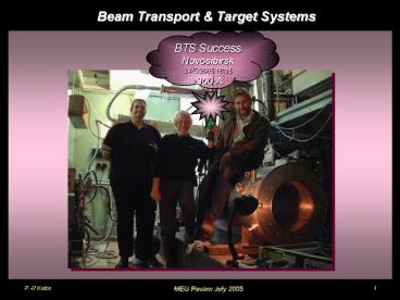
Beam Transport Target Systems
BTS Success Novosibirsk 24/5/2005 1815 300 A
2
Beam Line Target Status
- Topics to be Addressed
- Beam Transport System
- (i) Degrader / BTS optimization
- (ii) Layout - fixed
- Beam Line Components Status
- (i) Separator- undergoing
HV-conditioning - (ii) Beam Transport Solenoid BTS
being commissioned ?E5 - (iii) Vacuum System (beam line BTS)- being
assembled - (iii) Cryogenic Transfer Lines LN2 LHe
installed - He-Bag Target Systems
- Schedule 2005
- Summary Critical Points
3
Beam Transport System Status
4
Beam Transport System
As previously reported Beam Line
Commissioning 2004 concluded with phase space
measurements In vacuum up to the INJECTION into
the BTS (without BTS !!!)
Using real data ? SIMULATE Phase Space
Back-Track to Triplet II
? Forward-Track with Fringe Field of BTS
COBRA up to Target in COBRA
using GEANT
waist
Input Data to GEANT to study Degrader/Target
BTS/COBRA layout
5
Degrader BTS/COBRA Optimization
- Studied
- BTS/COBRA Distance vs. Degrader segmentation
Bfield - (Cryo.-Cryo. Gap) minimum (200 mm),
intermediate(300 mm), maximum(400 mm) - BTS/COBRA Polarity (/), (-/) radial
de-focussing/focussing
Max. Bve
Gap ?
Max. B-ve
- Weak Gap dependence (4)
- strong polarity dependence
- (15)
- Gap 400 mm
- -/ Polarity
- Degrader BTS
- strong degrader segmentation
- dependence (25)
6
Beam Transport System Layout
Distances Fixed Platform COBRA surveyed into
Zone
7
Beam Line Component Status
8
Component Status Separator
- MEG Vertical Separator
- Delayed by 8 weeks
- due to HV feed-through problems now solved
- HV (ve) supply changed to (ve) one - technical
- HV-electrode on top, want e deflected
down - !!! HV Conditioning Tests in front of ?E5
!!! - expected ready for beam time
Beam Upstream Side
Properties Vmax 200kV Dplates 19cm Leff
70cm
2371 mm
April 2005
May 2005
June 2005
9
Component Status BTS
- Beam Transport Solenoid BTS
- Schedule delayed by 7 weeks
- 5 weeks delay during manufacture
- 2 weeks transportation (papers stolen at
Russian border) - nevertheless
- !!! Novosibirsk Crew did a Very Good Job
!!! - BTS arrived PSI 8th July
Coil Manufacture - epoxying
Performance Tests Novosibirsk
End March 2005
End May 2005
10
BTS Performance Tests - Novosibirsk
- Performance Tests
- BINP Novosibirsk 21-29th May 2005
- Tested
- maximum Design Current (300 A)
- Quench Detection / Protection Systems
- (fast switch 30 ms 0.7? Shunt Resistor 90
power load) - Linearity Response (max. dev. 0.4)
- LHe Consumption Rate (3.6 l/hr)
- Magnetic Field Measurements
- Flexible Cryogenic Design via
- dedicated transfer lines (PSI)
- dewar operation (BINP)
- both (emergency)
All measurements tests successful
except Bfield measurements which were
influenced by steel support
structure
0.7? Shunt Resistor
11
Results BTS Performance Tests - Novosibirsk
Main Specifications LCryo 2810 mm DBore
380 mm DCoil 469.5 /
466.2 mm LCoil 2630 mm BMax
lt0.55 T Imax 300 amps LMax
0.98 H EStored 44 kJ
- Coils
- double layer
- cable dia. 1.23 mm
- 1865 / 1980 windings
- 40 NiTi
- RRR 100
BTOT deviates from expected due to Steel support
structure !!! Needs to be re-measured at PSI
!!! Acceptance Tests
Linearity (B vs. I) better 0.4 up to 300 A
12
BTS Preparations PSI
- Preparations for BTS Installation in
?E5 - cryogenic lines for LHe LN2 ready for
connection - valve chamber ready for mounting on BTS
- power supply tested ready
Valve Chamber Couples BTS to LHe transfer Line
contains Joule-Thompson Valves for control
LHe Transfer Line
Refrigerator unit Above ?E5
LHe line
13
BTS arrival PSI
8th July 2005
14th July 2005 ?E5
- BTS arrival PSI
- 8th July
- Acceptance Tests
- assembly / survey ?
- vacuum / leak tests ? ?
- cryogenic installation ?
- electrical installation ?
- cool-down
- quench detection /
- protection tests
- Bfield measurements
On route PSI 6500 km Novosibirsk - PSI
- !!! Problems !!!
- welding joint tower / cryostat
- damaged in transport
- ? Re-welded OK
- cryogenic connection valve-
- chamber / LHe transfer line
- not compatible
- ? To workshops
- Use dewar system LHe
Dmitry Reports 18th July 1100 coil
superconducting 2000 283A reached
(nominal 200A)
On route ?E5
14
He-Bag Target System Status
15
He-Bag / Target System - General
- (I) Desired Beam
Characteristics - transport maximum number µ to the target
(vacuum / He, large ?P) - maximize µ stopping-rate in the target
(small ?P, vacuum /He) - minimize beam spot size multiple
scattering (vacuum / He, degrader close to
target) - minimize background from decays or
Bremsstrahlung (degrader far from away, vacuum /
He) - (II) Desired
Target Requirements - depolarizing target (isotropic e, non-metal)
- minimum target size (low-Z)
- minimize material traversed by decay e ?
(slanted target) - minimize generation of annihilation photons
(large X0, low-Z e.g. CH2)
?
?
- Consequences
- vacuum window interface to COBRA
- He-atmosphere inside COBRA
- slanted, non-metallic, low-Z, large X0 target
16
COBRA-Environment
- (III) COBRA Environment
Requirements - thin vacuum window at entrance COBRA (190µ
Mylar) - safety measures against vacuum window rupture
(safety seals !!!) - must maintain DC TC dimensions insertion
concepts - stringent constant differential He-pressure
between DCs COBRA (few µb) - no He-leakage to TC PMs (N2-Bag)
- frequent / less frequent access to Downstream
side for calibration - monitoring purposes (
e.g. Cockroft-Walton, ?- CEX) - possibility to exchange targets ( LiF, LH2, CH2
etc.)
- Consequences
- Thin beam line Vacuum Window
- COBRA End-Cap Flanges HE-seals (US,DS)
- Target Insertion Tube support
- system (separate He-environment) (TISS)
- Target System (TS)
- ?
- PSI staged Engineering Design Project
- started design construction
- (i)US-flange, (ii) DS-flange, (iii) TISS, (iv)
TS - design Construction ready Feb. 2006
17
End-Cap Flanges He-Bag seals
Engineering Design Concept Upstream End-Cap
- Design
- Allows open
- access to TCs
- withdrawal
- without affecting
- He-environment
- Mounting
- N2-Bag
- TC-rails
- End-Cap
- He-Bag
- TCs
- Beam pipe
- with BTS
- Couple He-
- Bag rings to
- vac. window
He-Bag composition Sandwich CH2/EVAL/CH2
He-Bag inner sealing rings
18
Target Optics - momentum
Momentum-Spectrum Data whole Beam Line
optimized for each data point 2-D Scan for
each point !!! Theory ?-Kinematic Edge (29.79
MeV/c) Theoretical func. P3.5 folded with
Gaussian ?P/P Const. Cloud µ contribution ?
Fitted to data
Goal maximize stop-density (min. target
size) Question optimum beam momentum? Answer
28.2 MeV/c
- ? range vs. P
- (fixed ?P/P 7.7 FWHM)
- straggling 11
- characteristic P3.5
P3.5
straggling 11
Rel. ? stops
- ? Stopping Rate vs. P
- (fixed ?P/P 7.7 FWHM
- fixed 400? CH2 target)
- as p gt relative stop rate lt
- as p gt beam rate gt
- Optimal Stop Rate
- at P28.2 MeV/c
Norm. ?-stops
?2/dof 0.94 Pcent (28.16 ? 0.02) MeV/c ?P/P
(7.7 ? 0.3) FWHM Pbeam (28.2 ? 0.9)
MeV/c
P3.5
19
Target Optics - degrader
Many solutions studied 2 main categories
BTS
DMN
- (1) DNM Solution
- (190? Mylar Window)
- BTS / COBRA unlike
- polarities
- BBTS -3.55 kG
- degrader 480? CH2 at
- centre BTS
- beam ? 12.5 mm
COBRA
BTS
?P 4.2 MeV/c
? Beam envelope (cm)
?P 2 MeV/c
?P 4.5 MeV/c
- Transmission
- Efficiency
- TBTSDeg 98
- TBTSdegCOBRA 88
- TSepTIIClli 86.5
- Expected Stopping Rate
- R? 9.6107 ?/s
- at 1.8mA 4cm Tg
- (1.7108 ?/s at 1.8mA 6cm Tg)
Momentum Profile (MeV/c)
BTS
COBRA
? Beam divergence (mrad)
20
Target Optics degrader cont.
- (2) SNM Solutions ( no
degrader in BTS) -
(125? Mylar Window) - either combine Degrader Target (asymmetric
stop distribution) - or move degrader slightly upstream of target
(e.g. use as end-wall of target insertion tube)
- Conclusions SNM (no BTS degrader)
- Combined Soln gives ? 10 mm for 125? Mylar
Window - with 190 ? Mylar ? 11.5 mm
- no straggling loss only 3 decay loss
- Expected Rate R? 1.06108 ?/s at
1.8mA 4 cm Tg. - BUT annihilation radiation potential worse -
needs to be simulated - Upstream Soln gives similar results to DNM ?
12.5 mm - annihilation radiation potential worse - needs
to be simulated
upstream Deg. 15 cm
Combined Tg Deg
21
Target Insertion Tube
- Target Geometry ( for beam ? 10mm)
- LPROJ 150.4 mm, ? 21.8, a 60.3 mm, LTRUE
161.9 mm - material CH2 Rohacell / Mylar
- Slanted Target must be thicker multiple
scattering loss - on downstream-side !!!
- Target Simulation underway
- check of optimum angle ?
- dependence on target thickness (multiple
scattering, - background, acceptance, timing, resolution)
- material considerations
- decay particle hit distributions on end-cap
materials - associated background acceptance
22
Target Insertion Tube survey
- Target Insertion Tube Support System (TISS)
- Material
- Rohacell (PMI) closed cell foam, maybe EVAL
foil? - wall thickness probably 2 mm Rohacell 31
- length 1500 mm
- dia. 150 mm
- ? Weight 51 g
- simulations concerning background from
- e interactions in TISS underway
Target Insertion Tube
- Survey aspects
- target plane determined outside wrt. survey
markers - on rohacell support rings (laser tracker)
- possible temporary thin cross-wires on support
rings - for axial radial alignment (break
afterwards) - radial adjustment made with TISS end-flange
- axial position set by TISS (self-positioning)
?-target system
Flange lateral vertical move- ment
23
Schedule 2005
- Critical Path
- Commissioning Part 1 too short for BTS/COBRA
- phase space measurements ? Dec. Part 2
- final Target measurements ? first beam 2006
- Changes 2005 (compared to previous schedule)
- Separator schedule 8 weeks
- BTS Schedule 7 weeks
- COBRA end-cap target design manufacture
extended
24
Summary Critical Path
- Summary
- beam transport system up to COBRA defined
- COBRA Platform surveyed into position
- All beam transport elements now manufactured
- MEG Separator being conditioned
- BTS successfully tested in Novosibirsk
delivered PSI (8th July) - BTS reached current of 283A during commissioning
at PSI (18th July) - All cryogenic lines installed to zone
- all vacuum system available
- engineering project for COBRA end-caps target
Insertion support system underway - manufacture to be completed Feb. 2006
- Critical Points
- COBRA phase space measurement delayed until Dec.
2005 (delays Separator BTS) - Final measurements with target delayed until
first beam 2006
25
?-Beam Results (re-cap)
Provisional Results ?- Integral Spot
Rates MHz for 1,8mA Proton Current 4cm Target
E Normalized to Momentum Slit Settings
FS41L/R 250/280 FS43L/R 240/220
- First ?- Beam Studies with MEG Beam
- for calibration purposes in the experiment
- ?-p??0n, ?-p??n
- 55 ? 83 MeV ?s and 129 MeV ?s
- Data taken from
- P-spectrum measurements 25-33 MeV/c
- ?s detected above 30 MeV/c (pulse-ht. RF tof)
- dedicated ?- runs at 56 MeV/c 103 MeV/c
- 56 MeV/c interesting since max. momentum
- that can be transported to COBRA with
- good optics SNM in BTS
- dedicated CEX run at 112 MeV/c
e-
µ-
56 MeV/c R? 7.6 106 ?-/s slits open
R? 7.2 105 ?-/s slits70/70
?-
Recommended
