iso 50001 internal auditor training - PowerPoint PPT Presentation
Title:
iso 50001 internal auditor training
Description:
IAS Conducts the most recent and advanced IRCA Certified Lead Auditor program, ISO 50001 Internal Auditor Training Course is an Energy management system (EnMS) in India and the middle east such as Oman, Doha, Kuwait, Abudhabi, Sharjah… – PowerPoint PPT presentation
Number of Views:6
Title: iso 50001 internal auditor training
1
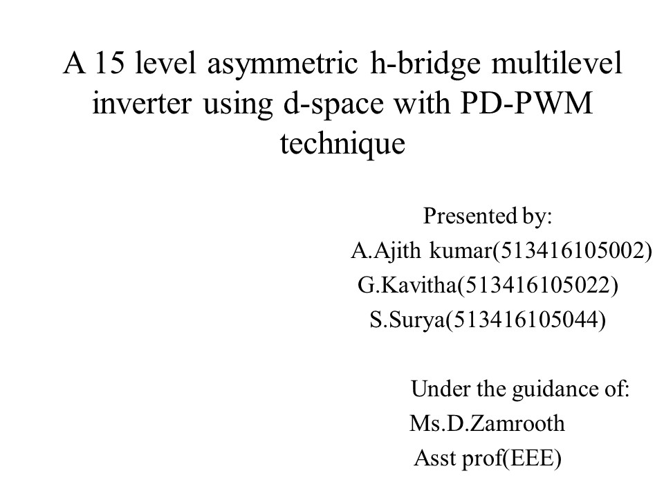
A 15 level asymmetric h-bridge multilevel
inverter using d-space with PD-PWM technique
- Presented by
- A.Ajith kumar(513416105002)
- G.Kavitha(513416105022)
- S.Surya(513416105044)
- Under the guidance of
- Ms.D.Zamrooth
- Asst prof(EEE)
2
ABSTRACT
- This paper presented a 15 level asymmetric
H-bridge multilevel inverter using a topology
with less number of switches. - In asymmetrical MLI, DC source magnitudes are
unequal and it is designed as to maintain a ratio
of 124. The modulation technique that has been
used here to get proper switching is PDPWM. - The input PWM signals have been generated using
MATLAB Simulink and real time simulation and
subsequent interface with hardware has been done
using d-SPACE and MicroLab Box (DS-1202).
3
INTRODUCTION
- MLI has ability to produce high power, medium
voltage and it reduces low switching loss and
total harmonic distortion(THD). - Neutral point clamped(NPC), Flying Capacitor(FC)
and Cascaded H-bridge(CHB) are the most common
multilevel topologies. - H-bridges are connected in a series to get
multilevel stepped waveform.
4
Literature survey
5
S NO YEAR AUTHOR TITLE DESCRIPTION
1 IEEE Transcation on 2012 Gautam Prakash shivam Novel h-bridge topology of MLI with reduced number of switches The topology is proposed for symmetrical and asymmetrical configuration . The technique used is POD-PWM The topology is carried for 5 level and THD reduced is approx 16.30
2 IEEE Transcation on 2015 Lakshmi Noby George Umashankar Kothari DP Cascaded 7 level inverter with reduced number of switches using Shifting PWM technique. The topology is of 7 level with 9 switch and 7 switch. The technique used is SPWM. The THD reduced is approx10.79
6
3 IEEE Transcation on 2016 Rajeevan Sivakumar Chintan patel Haithan abu-rub A 9 level inverter for medium voltage induction motor drive with open end stator end winding The proposed paper is of three phase 2 level voltage source inverter . It is employed by SVPWM and thus switching frequency is reduced half. It has ability to operate on both 5 and 3 levels. The THD approximately reduced is approx 9.08
7
Existing system
- The existing system of multilevel inverter is
cascaded MLI topology with minimum number of
switches. - The paper has been proposed on 15 level with 12p
switches and thus it results in reduction of
installation. - This structure consists of series connected
sub-multilevel inverters blocks. Three algorithms
for determination of magnitudes of dc voltage
sources have been presented. - The THD reduced is approx 10.09
8
Proposed System
- The operation of proposed MLI is to obtain
required voltage levels for industrial
applications. - The topology employs only seven switches.
- It effectively diminishes lower order harmonics
and thus effective reduction of THD is achieved
without using filters and is reduced approx 9.09 - PDPWM technique is used and thus generating by
d-space software and PIC16F877A controller it has
advantages of reducing the complexity for
generating PWM signals.
9
Block diagram
Dc source
H-bridge
Load
Voltage levelling
PWM Generation
PIC16F877A
Power Supply
10
Modulation technique
- The modulation technique used is PDPWM technique
and this topology comes under level shifted PWM. - In a PWM control, a fixed Dc voltage is given to
Inverter and controlled Ac output by adjusting
on/off period.
11
- PHASE DISPOSITION PULSE WIDTH
MODULATION(PDPWM) - In PDPWM, all carrier signals are in phase.
- The technique uses a sinusoidal wave of frequency
50Hz as reference that is compared with
triangular waves of frequency 5kHz. - The resultant PWM output then act as a gate
driver signal for MOSFET.
12
SIMULATION
13
Simulation for PWM Generation
14
GENERATION OF PD-PWM
15
SIMULATION RESULT ON 15 LEVEL
16
THD ANALYSIS ON CURRENT
17
THD ANALYSIS ON VOLTAGE
18
HARDWARE CIRCUIT
19
HARDWARE RESULT ON DSO
20
HARDWARE DESCRIPTION
- In order to make the real time interface, the
above subsystem is used in d-SPACE software. - PIC16F877A, platform with capability of producing
input voltage of 5V, has been used to generate
PWM signals. - The signals from controller are obtained in a DSO.
21
ADVANTAGES
- 1. Switching Frequency
- The multilevel inverter can operate at
both - fundamental switching frequencies that are
higher - switching frequency and lower switching
frequency. - 2.Input current
- Multilevel Inverters can draw input
current with low distortion. - 3.Harmonic distortion
- The THD becomes low in the output
waveform.
22
APPLICATION
- Motor drives
- Active filters
- Electric vehicle drives
- Dc power source utilization
- Power factor compensators
23
CONCLUSION
- The proposed multilevel inverter topology with
reduced number of switches can be implemented for
industrial drive applications. The basic
operation of the proposed multilevel inverter
topology and the mechanism to obtain the required
voltage level. In the proposed inverter topology
only ten switches are used which overcomes these
disadvantages of switching losses and circuit
complexity and it effectively diminishes lower
order harmonics. Therefore effective reduction of
total harmonic distortion is achieved.
24
Thank you

