
APOLLO GX50/55 GPS SAR Module Operations - PowerPoint PPT Presentation
Title:
APOLLO GX50/55 GPS SAR Module Operations
Description:
APOLLO GX50/55 GPS SAR Module Operations * * Used when fairly sure of the area. Extended line of the intended airport runways. Also specific lengths of highways ... – PowerPoint PPT presentation
Number of Views:108
Avg rating:3.0/5.0
Title: APOLLO GX50/55 GPS SAR Module Operations
1
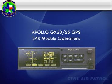
APOLLO GX50/55 GPSSAR Module Operations
2
Introduction
- This presentation is designed to introduce the
basics of the GX50/55 GPS - Focus will be placed on use of the GX50/55 for
CAP operations - This presentation is not designed to replace
hands on instruction or the owners manual - Always use your Quick Reference Guide for
assistance until you are proficient using this
equipment
3
GX50/55 Simulator
- The GX50/55 Deluxe simulator is available for
download from the Garmin website
http//www8.garmin.com/include/gxsimulator/Simul
atorPopupGX.html - You should use the simulator to gain proficiency
before you get in the airplane - Using the arrow keys on your keyboard you can fly
the simulator - The up and down arrows control speed and the left
right arrows control direction - Be sure that you have the SAR function checked
under the options menu before you turn the
simulator on
4
Apollo GX50 IFR enroute approach
certifiedApollo GX55 IFR enroute onlyApollo
GX60 Same as 50 plus com radioApollo GX65
Same as 55 plus com radio
Apollo Models
5
Knobology
6
Knobology
Chapters selected by the buttons and, Pages
viewed by scrolling with the large and small knobs
7
SAR Setup Page
You may need to verify the SAR module is activated
- Press MAP to reach the map functions
- Turn the LARGE KNOB to go to Map Setup
- Turn SMAL L KNOB to go to SAR Setup
- Press SEL to activate the flashing cursor
- Turn the SMALL KNOB to set SAR MAP ON
8
SAR Setup Page
For Parallel Searches using the Cell or LAT/LONG
grid system set GRID TYPE to BASIC and POSITION
to NW which covers all of the US
9
SAR Setup Page
Grid displays while in the BASCI (Cell or
Lat/Long) system
10
SAR Setup Page
- For Parallel Searches using the CAP Grid System
set GRID TYPE to US and POSITION to - GSW for the DFW area
- SAT for San Antonio area
- ELP for El Paso area
- HOU for Houston area
11
SAR Setup Page
Grid displays while in the US (CAP) system
12
SAR Setup Page
Grid displays while in the US (CAP) system
13
SAR Setup Page
Grid displays while in the US (CAP) system
14
SAR Setup Page
Grid displays while in the US (CAP) system
15
SAR Setup Page
Set Map Orientation to TRACK (Track Up)
Set Route Line to YES
16
SAR MAP
17
Marking a SAR Find or Waypoint
18
Marking a SAR Find or Waypoint
A screen showing your current position will
appear and it will ask you to name this SAR
Waypoint
Follow the same procedures as you would to name
any other waypoint -Inner Knob to change, Outer
Knob to move cursor, Enter to accept
Write down the SAR and Lat / Lon on your log
before you leave this screen. You want to be sure
that you have an accurate record of all possible
finds!
19
Marking a SAR Find or Waypoint
Note that the SAR Waypoint that we just created
does not show up on the SAR Map Screen when the
grids are being displayed. To see it on the map,
you have to either turn off the grid display or
turn the Outer Knob to one of the other Map
Screens.
Also note that the USR Soft Key has to be on to
see user waypoints. It is found on page 2 of the
Wide Screen or Split Screen Maps
20
SAR Search Patterns
The SAR Module will automate the flying of four
search patterns
- Route Search with offset
- Creeping Line Search
- Expanding Square Search
- Parallel or Grid Search
21
Route Search Setup
22
Route Search Setup
23
Route Search Setup
24
Route Search Setup
25
Route Search Setup
Activate the Flight Plan (FPL)
26
Route Search Setup
Set the Route Offset
27
Creeping Line Search Setup
28
Creeping Line Search Setup
29
Creeping Line Search Setup
30
Creeping Line Search Setup
31
Creeping Line Search Setup
32
Creeping Line Search Setup
33
Creeping Line Search Setup
34
Creeping Line Search Setup
35
Creeping Line Search Setup
36
Expanding Square Search Setup
Spacing is constant but leg length increases with
each turn
37
Expanding Square Search Setup
38
Expanding Square Search Setup
39
Expanding Square Search Setup
40
Expanding Square Search Setup
41
Expanding Square Search Setup
42
Expanding Square Search Setup
43
Expanding Square Search Setup
44
Parallel (Grid) Search Setup
CAP or Conventional Grid System
45
Parallel (Grid) Search Setup
CAP or Conventional Grid System
1
Full 15x15 grid is subdivided into four
7.5x7.5 minute grids labeled A-B-C-D
2
A
B
The Apollo SAR software further designates the
entry point corners of the grid as 1-2-3-4
C
D
3
4
46
Parallel (Grid) Search Setup
- For Parallel Searches using the CAP Grid System
set GRID TYPE to US and POSITION to - GSW for the DFW area
- SAT for San Antonio area
- ELP for El Paso area
- HOU for Houston area
47
Parallel (Grid) Search Setup
Parallel Search using CAP Grid System
48
Parallel (Grid) Search Setup
Parallel Search using CAP Grid System
Turn the SMALL KNOB until you see the Parallel
Line page then press ENTER
49
Parallel (Grid) Search Setup
Parallel Search using CAP Grid System
- Press SEL then use the SMALL KNOB to change data
the LARGE KNOB to move the flashing cursor - Set the Grid (and sub-grid if needed) and the
entry point corner 1 NW, 2 NE, 3 SE, 4
SW - Set the track spacing (0.2 5.0 NM)
- Set the search track direction N/S or E/W
50
Parallel (Grid) Search Setup
Parallel Search using CAP Grid System
Press ENTER to accept your entry and ENTER again
to return to the map page where your Parallel
Search is shown The data is sent to the GPS CDI
and the GPS will call your turns based on your
current speed via the MSG function
51
Parallel (Grid) Search Setup
New, Cell, or LAT/LONG Grid System
Currently used in Texas Wing
52
Parallel (Grid) Search Setup
For Parallel Searches using Cell or LAT/LONG set
GRID TYPE to BASIC and POSITION to NW which
covers all of the US
53
Parallel (Grid) Search Setup
Parallel Search using Cell Grid System
Turn the SMALL KNOB to the SAR Position
page Press SEL and use the SMALL KNOB to change
the data and the LARGE KNOB to move the flashing
cursor Set the LAT/LONG to the 100 x 100 grid
nearest your search area and press ENTER to accept
54
Parallel (Grid) Search Setup
Parallel Search using Cell Grid System
55
Parallel (Grid) Search Setup
Parallel Search using Cell Grid System
Turn the SMALL KNOB until you see the Parallel
Line page then press ENTER
56
Parallel (Grid) Search Setup
Parallel Search using Cell Grid System
100
90
40
97
101
37
30
33
57
Parallel (Grid) Search Setup
Parallel Search using Cell Grid System
97
98
34
37BC3
33
33 Lat and 97 Long
58
Parallel (Grid) Search Setup
Parallel Search using Cell Grid System
- Press SEL then use the SMALL KNOB to change data
the LARGE KNOB to move the flashing cursor - Set the Grid to 37BC1
- Set the track spacing (0.2 5.0 NM)
- Set the search track direction N/S or E/W
59
Parallel (Grid) Search Setup
Parallel Search using Cell Grid System
Press ENTER to accept your entry and ENTER again
to return to the map page where your Parallel
Search is shown The data is sent to the GPS CDI
and the GPS will call your turns based on your
current speed via the MSG function
60
Questions?
Recommended
CrystalGraphics Presentations


