
Fingerprint Recognition PowerPoint PPT Presentation
Title: Fingerprint Recognition
1
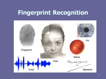
Fingerprint Recognition
2
Summary
3
Lecture Plan
- Motivation
- History of fingerprints
- Fingerprint sensing
- Fingerprint features
- Fingerprint matching
4
User Convenience
Heavy Web users have an average of 21 passwords
81 of users select a common password (the most
common password is the word password) and 30
write their passwords down or store them in a
file. (2002 NTA Monitor Password Survey)
5
Embedded Fingerprint Systems
6
Applications
- Security authentication
- Forensic sciencesindividualization
7
Applications
8
Fingerprint Recognition
- Motivation
- History of fingerprints
- Fingerprint sensing
- Fingerprint features
- Fingerprint matching
9
History of fingerprints
- Use of fingerprints to associate a person with an
event or transaction can be traced to ancient
China, Babylonia and Assyria as early as 6,000
BC.
10
Archaelogical remains
11
History of fingerprints
- 1750 B.C.- people in Babylon used fingerprints
to sign their identity on clay tablets - 300 B.C.-Emperors of China used personalized clay
seals - In 1686, Marcello Malpighi, an anatomy professor
at the University of Bologna, wrote in a paper
that fingerprints contained ridges, spirals and
loops. - In 1856, Sir William Herschel, a British
Magistrate in Jungipoor, India, used fingerprints
(actually palmprints) to certify native
contracts.
12
History of fingerprints
- During the 1870s, Dr. Henry Faulds, a British
surgeon in Japan, after noticing finger marks on
ancient pottery, studied fingerprints, recognized
the potential for identification, and devised a
method for classifying fingerprint patterns. - 1880 -Faulds published an article in "Nature,"
discussing fingerprints as a means of personal
identification. He is also credited with the
first fingerprint identification of a greasy
fingerprint left on an alcohol bottle.
13
(No Transcript)
14
History of fingerprints
- In 1880, Alphonse Bertillon, a Paris police
department employee and son of an anthropologist,
developed a system of anthropometry as a means
for classifying criminals and used this system to
identify recidivists. - Anthropometry (a system of cataloging an
individual's body measurements such as height,
weight, lengths of arm, leg, index finger etc.)
was shown to fail in a famous case at Leavenworth
Prison, where two prisoners, both named William
West, were found to have nearly identical
measurements even though they claimed not to be
biologically related. - 1892Juan Vucetich (Argentina) made the first
criminal fingerprint identification
15
History of fingerprints
- Francis Galton, an anthropologist, began a
systematic study of fingerprints as a means of
identification in the 1880s. - In 1892, he published the first book on
fingerprints. - In 1897, Sir Edward Henry, a British police
officer in India, established a modified
fingerprint classification system using Galton's
observations. This system was ultimately adopted
by Scotland Yard in 1901 and is still used in
many English-speaking countries.
16
History of fingerprints
- 1924-an act of U.S. Congress established the
Identification Division of the FBI (Federal
Bureau of Investigation) with a database of 810
000 fingerprint cards - Most of the early fingerprint identification
systems were put into place in major metropolitan
areas or as national repositories. Juan Vucetich
established a fingerprint file system in
Argentina in 1891, followed by Sir Edward Henry
in 1901 at Scotland Yard in England.
17
Classification Manual Card Files
- Manual fingerprint card files were usually
organized by a pattern. Classification system
based on combination of the patterns on each of
the ten fingers of individuals. - Two similar classification systems were
developed, one by Sir Edward Henry in UK and one
by Juan Vucetich in Argentina. The Henry system
became a standard for many countries outside
South America, while the Vucetich system was used
in South America.
18
Classification Manual Card Files
- In the Henry classification system, numerical
weights are assigned to fingers with a whorl
pattern. A bin number, based on the sum of the
weights for the right hand and sum of the weights
for the left hand is computed to generate 1,024
possible bins. Letter symbols are assigned to
fingers capital letters to the index fingers and
lower-case letters to other fingers. - These are combined with the numeric code to
further - subdivide the 1,024 bins. Each of these pattern
groupings defines bins into which fingerprint
cards with the same pattern group are placed. - A bin might be a folder in a file drawer or
several file drawers if it contains a common
pattern group and the file is large.
19
Classification
- Two problems existed in manual files
- first, the patterns assigned to each finger might
not be exactly the same on each occurrence of the
same card - second, if a pattern type error was made, the
search might not reach the correct bin. - In the early stages of automation, the accuracy
of the manual fingerprint system was estimated to
be only 75. - To further complicate matters, the distribution
of pattern types is not uniform thus there were
a few bins that contained most of the fingerprint
cards. For example, nearly 65 of fingers have
loop patterns, 30 have whorl patterns and only
5 have arch patterns.
20
Classification
- Fingerprint patterns comprise of loops (left or
right), whorls and arches. The patterns are
differentiated based on the presence of zero, one
or two delta regions. - A delta region is defined by a tri-radial
ridge direction at a point. Arch patterns have no
delta, loops have one delta, and whorls have two
deltas.
Some of the common fingerprint types. The core
points are marked with solid white circles while
the delta points are marked with solid black
circles.
21
Fingerprints
- The inside surfaces of hands and feet of humans
(and, in fact, all primates) contain minute
ridges of skin with furrows between each ridge - The purpose of this skin structure is to
- Facilitate exudation of perspiration
- Enhance sense of touch
- Providing a gripping surface
22
Fingerprint Recognition
- Motivation
- History of fingerprints
- Fingerprint sensing
- Fingerprint features
- Fingerprint matching
23
Fingerprints
- Fingerprints are "permanent" in that they are
formed in the fetal stage and remain throughout
the life time. - The changes can be due to skin flexibility,
growing, scarring, a wound, etc. - They are only weakly determined by genetics, e.g.
identical (monozygotic, one egg) twins (the same
DNA) have fingerprints that are quite different - Fingerprints of an individual are unique
- The right definition of a fingerprint originates
from the print (stamp) that finger left on an
object.
24
Matching
- Fingerprint matching prior to automation involved
the manual examination of the so-called Galton
details (ridge endings, bifurcations, lakes,
islands, pores etc. collectively known as
"minutiae"). - Prior to the late 1960s, neither the available
computer - systems that could display fingerprint images for
comparison were affordable, nor a significant
number of digital fingerprint images were
available for display. Consequently, the
comparison was manual, requiring a magnification
glass for comparing the features of the many
candidate prints manually retrieved from the
database files.
25
Early Automation Efforts
- US NBS/NIST Research In the mid-1960s, the
National Institute of Standards and Technology
(NIST) initiated several research projects to
automate the fingerprint identification process.
The efforts were supported by the Federal Bureau
of Investigation (FBI) as part of an initiative
to automate many of the processes in the Bureau. - Royal Canadian Police By the mid-1960s, the
fingerprint collection of the Royal Canadian
Mounted Police (RCMP) had grown to over a million
tenprint records. The video-file system was
operational until the mid-1970s, when the RCMP
installed the first automated fingerprint
identification system (AFIS).
26
Early Automation Efforts
- FBI In the USA, at about the same time that the
RCMP and the UK Home Office were looking for
automation technologies, the FBI was
investigating the possibilities for automating
the fingerprint identification operations. In the
mid-1960s, the FBI signed research contracts with
3 companies to build a working prototype for
scanning FBI fingerprint cards, completed by the
early 1970s. - United Kingdom In the UK, over about the same
time-scale as the FBI, the Home Office was
working within its own Scientific Research and
Development Branch (SRDB). - Japan The Japanese National Police (JNP) who had
a fingerprint file of over six million records,
also initiated study of the automation
possibilities.
27
Further Development
- During the 1970s, the FBI contracted with a
number of organizations as well as developed
their own research organization to manage the
numerous projects that lead the way to the
Integrated Automated Fingerprint Identification
System (IAFIS). - The transition to a large-scale imaging
application environment provided enormous
challenges for everyone at that time, but it was
especially challenging for the FBI to implement a
system to manage up to 35,000 image-based
transactions per day. - The efforts put into AFIS interoperability by
NIST under the FBI sponsorship resulted in an
ANSI/NIST standard for data interchange. This
standard was initially crafted in mid-1980, is
updated every 5 years and defines data formats
for images, features and text. - Outside North America, under the auspices of the
Interpol AFIS Expert Working Group (IAEG), there
is a similar effort toward interchange
standardization following the basic format of the
ANSI/NIST standard.
28
Civil Commercial Applications
- Civil
- Welfare Fraud Reduction
- Border Control
- Driver registration
- Commercial
- Miniaturized Sensors
- Personal Access Protection
- Banking Security
- Business-to-Business Transactions
29
Scanning and Digitizing
- The FBI initiated a research program to build an
engineering model of a scanner that could sample
an object area of 1.5 X 1.5 in at 500 pixels per
inch (DPI), with an effective sampling spot size
of 0.0015 in, signal-to-noise ratio (S/N) in
excess of 1001 and digitized to at least 6 bits
(64 gray levels). - In the late 1960s, these requirements could only
be met by a system that used a cathode ray tube
and a precision deflection system, an array of
tubes that measure and reflected light, and
amplifier-digitizer to convert the electrical
signal into a digital value for each pixel. - There were relatively few scanning devices by the
late 1970s that met the technical characteristics
requirements of 500 dpi, a 0.0015 inch effective
sample size, greater than 100 S/N noise ratio and
a 6 bit dynamic range. - It ten more years the scan quality standards were
set by IAFIS, which is the current benchmark for
scanning of fingerprint images, requiring 200 or
more gray levels.
30
Scanning and Digitizing
- Today, there are reasonably priced scanners that
are capable of scanning a 1.5 X 1.5 inch
fingerprint area at 1,000 (or more) DPI with a
digitizing range of 10 or 12 bits, S/N ratio in
excess of 1001. Most of the fingerprint input
devices now used in both criminal and civil
fingerprint systems directly scan the fingerprint
from the finger. These are "live-scan" capture
devices. - The most recent American National Standards
Institute (ANSI) standard for fingerprint data
interchange recommends 1,000 DPI resolution to
yield greater definition of minute fingerprint
features. - In many cases, the live-scan finger scanning
devices are implemented using optical (FTIR and
scattering) techniques, using planar fabrication
techniques to build capacitor arrays and
ultrasound transducers.
31
Scanning and Digitizing
The general structure of a fingerprint scanner is
shown below. A sensor reads the finger surface
and converts the analogue reading in the digital
form through an A/D (Analog to Digital)
converter. An interface module is responsible
for communicating messages with external devices
(e.g., a personal computer).
32
Characteristics of Fingerprint Images
- Resolution This indicates the number of dots or
pixels per inch (dpi). - Area The size of the rectangular area sensed by
a fingerprint scanner is a fundamental parameter.
The larger the area, the more ridges and valleys
are captured and the more distinctive the
fingerprint becomes. - Number of Pixels This can be derived from the
resolution and the fingerprint area. A scanner
working at r dpi over an area of height (h) X
width (w) inch2 has rh X rw pixels. - Dynamic range (or depth) This denotes the number
of bits used to encode the intensity value of
each pixel. - Geometric accuracy This is specified by the
maximum geometric distortion introduced by the
acquisition device, and expressed as a percentage
with respect to x and y directions. - Image quality The image quality depends on the
quality of scanner and also on the intrinsic
finger status. When the ridge prominence is very
low (for manual workers, elderly people), or
fingers are too moist or too dry, most scanners
produce poor quality images.
33
Scanning and Digitizing
34
Fingerprint images
Optical scanner Capacitive scanner
Piezoelectric scanner
Thermal scanner Inked impression Latent
fingerprint
35
Fingerprint Scanners and their Features
- Interface FBI-compliant scanners often have
analogue output and a frame grabber is necessary
to digitize the images. This introduces an extra
cost and usually requires an internal board to be
mounted in the host. In non-AFIS devices, the
analogue-to-digital conversion is performed by
the scanner itself and the interface to the host
is usually through a simple Parallel Port or USB
connection. - Frames per second This is the number of images
the scanner is able to acquire and send to the
host in a second. - Automatic finger detection Some scanners
automatically detect the presence of a finger on
the acquisition surface, without requiring the
host to continually grab and process frames this
allows the acquisition process to be
automatically initiated as soon as the users
finger touches the sensor. - Encryption This is the securing of the
communication channel between the scanner and the
host. - Supported operating systems Compatibility with
more operating systems is an important
requirement.
36
Fingerprint Sensing
- The most important part of a fingerprint scanner
is the sensor. - Sensors belong to one of the three families
- Optical sensors
- Frustrated Total Internal Reflection (FTIR)
- FTIR with a sheet prism
- Optical fibers
- Electro-Optical
- Solid-state sensors
- Thermal
- Electric field
- Piezoelectric
- Ultrasound sensors
37
Fingerprint Sensing optical FTIR
- Frustered Total Internal Reflection (FTIR)
- The oldest and most used livescan technique. The
finger touches the top side of a glass prism, but
while the ridges enter in contact with the prism
surface, the valleys remain at a certain
distance. The left side of the prism is
illuminated through a diffused light which is
reflected at the valleys and randomly scattered
(absorbed) at the ridges. The lack of reflection
allows the ridges (appear dark) to be
discriminated from the valleys (appear bright).
The light rays exit from the right side of the
prism and are focused through a lens onto a CCD
or CMOS image sensor. Because FTIR devises sense
a 3D surface, they cannot be easily deceived by a
photograph or printed image of a fingerprint.
38
Fingerprint Sensing FTIR with a sheet prism
FTIR with a sheet prism Using a sheet prism
made of a number of prismlets adjacent to each
other, instead of a single large prism, allows
the size of the mechanical assembly to be reduced
to some extent. However, the quality of the
acquired images is generally lower than the
traditional FTIR techniques using glass prisms.
39
Optical Fibers
A significant reduction of the packaging size
can be achieved by substituting prism and lens
with a fiber-optic platen. The finger is in
direct contact with the upper side of the platen
on the opposite side, a CCD or CMOS, tightly
coupled with the platen, receives the finger
residual light conveyed through the glass fibers.
Unlike the FTIR devices, the CCD/CMOS is in
direct contact with the platen and therefore its
size has to cover the whole sensing area. This
may result in a high cost for producing large
area sensors.
40
Electro-Optical
- Electro-optical sensors contain light-emitting
polymer instead of a prism that activates the
photodiode array embedded in glass to obtain
fingerprint image.
41
Optical Sensors
42
Solid State Sensing
Thermal These sensors are made of pyro-electric
material that generates current based on
temperature differentials. The fingerprint
ridges, being in contact with the sensor surface,
produce a different temperature differential than
the valleys, which are away from the sensor
surface. The sensors are typically maintained at
a high temperatures. Electric Field The
sensor consists of a drive ring that generates a
sinusoidal signal and a matrix of active antennas
that receives a very small amplitude signal
transmitted by the drive ring and modulated by
the derma structure (subsurface of the finger
skin). The finger must be simultaneously in
contact with the sensor and the drive ring. To
image a fingerprint, the analogue response of
each element in the sensor matrix is amplified
and digitized. Piezoelectric
Pressure-sensitive sensors produce an electrical
signal when mechanical stress is applied to them.
The sensor surface is made of a non-conducting
dielectric material which generates a small
amount of current. Since ridges and valleys are
present at different distances from the sensor
surface, result in different currents.
43
Ultrasound sensors
Ultrasound sensing is based on sending acoustic
signals toward the fingertip and capturing the
echo signal. The echo signal is used to compute
the range image of the fingerprint and
subsequently, the ridge structure itself. This
method images the subsurface of the finger skin
(even through thin gloves). Therefore, it is
resilient to dirt and oil accumulations that may
visually mar the fingerprint. However, the
scanner is large with mechanical parts and quite
expensive. Moreover, it takes a few seconds to
acquire an image.
44
Fingerprint Sensing sweep systems
- Sweep systems
- Touch systems
45
Image reconstruction from slices
- The touch method is most commonly used with
sensors wherein the finger is simply put on the
scanner, without moving it. - To reduce costs, especially in silicon sensors,
another sensing method has been proposed to
sweep the finger over the sensor. Since the
sweeping consists of a vertical movement only,
the chip must be as wide as a finger on the
other hand, in principle, the height could be as
low as one pixel. At the end of the sweep, a
single fingerprint image is reconstructed from
the slices.
46
Image reconstruction from slices
- The sweep method allows the cost of a sensor to
be significantly reduced, but requires - reliable reconstruction to be performed. The main
stages of the reconstruction are - Slice quality computation For each slice, a
single global quality measure and several local
measures are compared by using an image contrast
estimator. - Slice pair registration For each pair of
consecutive slices, the only possible
transformation is assumed to be a global
translation ?x, ?y, where the ?y component is
dominant, but a limited ?x is also allowed to
cope with lateral movements of the finger during
sweeping. - Relaxation When the quality of slices is low,
the registration may fail and give incorrect
translation vectors. Assuming a certain
continuity of the finger speed during sweeping
allows analogous hypotheses to be generated on
the continuity of the translation vectors. The
translation vectors continuity may be obtained
through a method called relaxation which has the
nice property of smoothing the samples without
affecting the correct measurements too much. - Mosaicking The enhanced translation vectors
produced by the relaxation stage are used to
register and superimpose the slices. Finally,
each pixel of the reconstructed output image is
generated by performing a weighted sum of the
intensities of the corresponding pixels in the
slices.
47
Image reconstruction from slices
48
Sensing Area vs. Accuracy
- The cost of a sensor increases with increase in
size of sensing area. - With smaller areas, the identification accuracy
may deteriorate.
49
Quality of images
Good quality fingerprint
Intrinsically bad fingerprint
Dry finger
Wet finger
50
Different scanners ideal conditions
51
Different scanners bad conditions
52
Compressing Fingerprint Images
- The Wavelet Scalar Quantization (WSQ) is an
effective compression - technique (achieves compression ratio of 10 to
25). - The WSQ encoder performs the following steps
- The fingerprint image is decomposed into a number
of spatial frequency sub-bands (typically 64)
using a Discrete Wavelet Transform (DWT). - The resulting DWT coefficients are quantized into
discrete values results in some loss of
information. - The quantized sub-bands are concatenated into
several blocks (typically three to eight) and
compressed using an adaptive Huffman run-length
encoding.
53
Compressing Fingerprint Images
54
Fingerprint Recognition
- Motivation
- History of fingerprints
- Fingerprint sensing
- Fingerprint features
- Fingerprint matching
55
Fingerprint verification and identification
56
Coarse representation Level 1 features
57
Coarse representation Level 1 features
- Left loop Right loop Whorl
Arch Tented Arch
58
Minutiae Level 2 features
59
Minutia Level 2 features
60
Level 3 features
Sweat pores
61
Level 3 features
62
Minutiae Detection
Original image Binary image Skeleton
and extracted
minutiae
63
Feature extraction process
Fingerprint area Frequency image Orientation image
- Fingerprint image
Ridge pattern Minutiae points
64
Feature extraction process
65
Orientation image of fingerprint
- Computation of gradients over a square-meshed
grid of size 16 x 16 the element length is
proportional to its reliability.
66
Orientation image of fingerprint
67
Frequency image
- Ridge frequency inverse of the average distance
between 2 consecutive peaks
68
Segmentation
- Segmentation is the process of isolating
foreground from background - Image block (16x16 pixels) decomposition
- Thresholding using variance of gradient for each
block
69
Why do we need enhancement?
70
Why do we need enhancement?
71
Need for Enhancement
72
Enhancement
- Initial enhancement may involve the normalization
of the inherent intensity variation in a
digitized fingerprint caused either by the inking
or the live-scan device. - One such process - local area contrast
enhancement (LACE) is useful to provide such
normalization through the scaling of local
neighborhood pixels in relation to a calculated
global mean.
- An inked fingerprint image
- The results of the LACE algorithm on (a)
Histograms of fingerprint images in (a) and (b)
above.
73
Enhancement
- Another type of enhancement is contextual
filtering that - 1. Provide a low-pass (averaging) effect along
the ridge direction with the aim - of linking small gaps and filling impurities
due to pores or noise. - 2. Perform a bandpass (differentiating) effect in
a direction orthogonal to the ridges to increase
the discrimination between ridges and valleys and
to separate parallel linked ridges. - 3. Gabor filters have both frequency-selective
and orientation-selective properties and have
optimal joint resolution in both spatial and
frequency domains.
74
Enhancement
Graphical representation (lateral and top view)
of the Gabor filter defined by the parameters ?
1350, f 1/5, sx sy 3
75
Enhancement
- The simplest and most natural approach for
extracting the local ridge orientation field
image, D, containing elements ?ij, in a
fingerprint image is based on the computation of
gradients in the fingerprint image. The gradient
delta(xi, yj) at point xi, yj of fingerprint
image I, is a two-dimensional vector - deltax(xi, yj), deltay(xi, yj), where
deltax and deltay components are the derivatives
of I in xi, yj with respect to x and y
directions respectively.
76
Enhancement
- The local ridge frequency (or density) fxy at
point x, y is the inverse of the number of
ridges per unit length along a hypothetical
segment centered at x, y and orthogonal to the
local ridge orientation ?xy. A frequency image F,
analogous to the orientation image D, can be
defined if the frequency is estimated at discrete
positions and arranged into a matrix. The local
ridge frequency varies across different fingers,
and even regions. The ridge pattern can be
locally modeled as a sinusoidal-shaped surface
and the variation theorem can be exploited to
estimate the unknown frequency.
77
Enhancement
The variation of the function h in the interval
x1, x2 is the sum of the amplitudes a1, a2,
a8. If the function is periodic or the function
amplitude does not change significantly within
the interval of interest, the average amplitude
am can be used to approximate the individual a.
Then the variation can be expressed as 2am
multiplied by the number of periods of the
function over the interval.
78
Gabor filters
79
Enhancement Results
80
Artifacts
81
Post-processing
82
Extraction of minutiae
- count the number of ridge pixels in the window
83
Feature extraction errors
- The feature extraction algorithms are imperfect
and often introduce measurement errors - Errors may be made during any of the feature
extraction stages, e.g., estimation of
orientation and frequency images, detection of
the number, type, and position of the
singularities and minutiae, segmentation of the
fingerprint area from background, etc. - Aggressive enhancement algorithms may introduce
inconsistent biases that perturb the location and
orientation of the reported minutiae from their
gray-scale counterparts - In low-quality fingerprint images, the minutiae
extraction process may introduce a large number
of spurious minutiae and may not be able to
detect all the true minutiae
84
Fingerprint Recognition
- Generalities and Applications
- Fingerprints and their images
- History of fingerprints
- Fingerprint sensing
- Fingerprint features
- Fingerprint matching
85
Intra-variability
- Matching fingerprint images is an extremely
difficult problem, mainly due to the large
variability in different impressions of the same
finger (intra-variability). The main factors are - Displacement (global translation of the
fingerprint area) - Rotation
- Partial overlap
- Non-linear distortion
- the act of sensing maps the three-dimensional
shape of a finger onto the two-dimensional
surface of the sensor - skin elasticity
- Pressure and skin condition
- Noise introduced by the fingerprint sensing
system - Feature extraction errors
86
Matching illustration
Examples of mating, non-mating and multiple
mating minutiae.
87
Matching illustration
An example of matching the search minutiae set in
(a) with the file minutiae set in (b) is shown in
(c).
88
Difficulty in fingerprint matching
- Small overlap
- Non-linear distortion
- Different skin conditions
89
Finger placement
- A finger placement is correct when the user
- Approaches the finger to the sensor through a
movement that is orthogonal to the sensor surface - Once the finger touches the sensor surface, the
user does not apply traction or torsion
90
Non-linear distortion
91
Non-linear distortion
- Three distinct regions
- A close-contact region (a) where the high
pressure and the surface friction do not allow
any skin slippage - A transitional region (b) where an elastic
distortion is produced by skin compression and
stretching - An external region (c) where the light pressure
allows the finger skin to be dragged by the
finger movement
92
Fingerprint Matching
- Minutiae-based matching finding the alignment
between the template and the input minutiae sets
that results in the maximum number of minutiae
pairings - Correlation-based matching correlation between
corresponding pixels is computed for different
alignments (e.g. various displacements and
rotations) - Ridge feature-based matching comparison in term
of features such as local orientation and
frequency, ridge shape, texture information, etc.
93
Local minutiae matching
94
Minutiae correspondence
95
Pre-alignment
- Absolute pre-alignment
- The most common absolute pre-alignment technique
translates and rotates the fingerprint according
to the position of the core point and the delta
point (if a delta exists) - Relative pre-alignment
- By superimposing the singularities
- By correlating the orientation images
- By correlating ridge features (e.g. length and
orientation of the ridges)
96
Fingerprint matching with absolute pre-alignment
- First align the fingerprints using the global
structure. - Extract the core-points (prominent symmetry
points) to estimate the transformation parameters
v, ? (v from the difference in their position,
and ? from the difference in their angle) by
complex filtering of the smoothed orientation
field. - Then use the local structure for point-to-point
matching.
Input image Template image
97
Minutiae matching with relative pre-alignment
- Pre-alignment based on the minutiae marked with
circles and the associated ridges - Matching results where paired minutiae are
connected by green lines
98
Ridge count
99
Triangular matching
100
Correlation based matching
- Non-linear distortion makes fingerprint
impressions significantly different in terms of
global structure two global fingerprint patterns
cannot be reliably correlated - Due to the cyclic nature of fingerprint patterns,
if two corresponding portions of the same
fingerprint are slightly misaligned, the
correlation value falls sharply - A direct application of 2D correlation is
computationally very expensive
101
Ridge feature-based matching
- Most frequently used features for fingerprint
matching - Orientation image
- Singular points (loop and delta)
- Ridge line flow
- Gabor filter responses
102
Comparison of Biometric Technologies
103
Fingerprint Recognition
- Strengths
- It is a mature and proven core technology,
capable of high levels of accuracy - It can be deployed in a range of environments
- It employs ergonomic, easy-to-use devices
- The ability to enroll multiple fingers can
increase system accuracy and flexibility
- Weaknesses
- Most devices are unable to enroll some small
percentage of users - Performance can deteriorate over time
- It is associated with forensic applications
104
References and Links
- Signal Processing Institute, Swiss Federal
Institute of Technology - http//scgwww.epfl.ch/
- Biometric Systems Lab, University of
- Bologna
- http//bias.csr.unibo.it/research/biolab/
Recommended
