
The Integrated Chip PowerPoint PPT Presentation
1 / 34
Title: The Integrated Chip
1
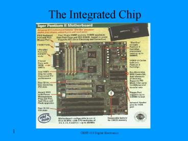
The Integrated Chip
2
Interest
- The IC chip has been the driving force in the
computer race for smaller parts. The most
powerful chip available to the consumer is the
Intel Pentium 4 chip.
3
Logic Levels
- Voltage characteristics of TTL (Transistor-Transis
tor Logic) and CMOS ICs (Complimentary Metal
Oxide Semiconductor Integrated Circuits) - Logical 0 (Low) Ground-.8V
- Logical 1 (High) 2- 5.5V
- Symbol
4
Logic Levels Continued
- Voltage characteristics of CMOS logic families.
- 4000 and 74C00 series.
- Logical 0 (Low) Ground-.5V
- Logical 1 (High) 7-10V
- Symbol
CMOS
- Advantages
- Low power requirements
- Good noise immunity
5
Noise
- Noise immunity (noise margin) Circuits
insensitivity or resistance to undesired voltages
or noise. - Noise margin comparison TTL vs. CMOS
CMOS
Noise Margin (1.5V)
Noise Margin (.4V)
Noise Margin (1.5V)
Noise Margin (.4V)
6
Noise
- In a digital circuit, noise is unwanted voltages.
- In actual practice, the noise is greater because
the voltage must be increased to the switching
threshold. - Switching actually occurs in the undefined
region. Varies widely by manufacturer,
temperature and quality of chip.
7
Other Digital IC Specifications
- Drive capacities
- IC fan out The of inputs that be driven off a
gates output. (i.e. 1 output can drive 10 inputs) - TTL ICs 10
- Low Power Schottkty TTL 20
- 4000 series CMOS 50
- IC fan in (input loading characteristics) Load
represented by a single gate. Each IC family
different. - Propagation delay Slight delay between the time
the input changes and the time the output
changes. - Power dissipation As propagation delay decreases
(increased speed), the power consumption and heat
generation increases.
8
MOS ICs
- Metal Oxide Field Effect Transistor (MOSFET) is a
primary component in MOS ICs. - Metal Oxides SMOCN Strontium, Manganese,
Oxides, Cobalt, Nickel - Advantages Smaller, consume less power, better
noise margin and higher fan-out. - Disadvantages Lack of speed.
- MOS devices use less space, have more function
per chip then bipolar ICs (TTL). - PMOS (P channel MOS)
- NMOS (N channel MOS) Newer faster.
- Examples Microprocessors, memory clock chips
9
CMOS ICs
- Complementary Metal Oxide Semiconductor (CMOS)
- Advantages Low power consumption, low cost,
simple design, low heat dissipation, good
fan-out, wide logic swings, and good noise margin
performance, operate on wide range of voltages. - Disadvantages slower then bipolar ICs (TTL),
more susceptible to ESD - FACT CMOS ICs more tolerant of ESD.
- Ideal for battery operated portable devices
because of low power consumption. (i.e.
wristwatches laptops)
10
Prevent ESD in CMOS ICs
- Use conductive foam to store ICs
- Ground solder iron tip
- Remove IC with power off.
- Ensure input signals do not exceed power supply
voltages. - Turn off input signals before circuit power is
turned off. - Connect all unused input leads to power supply
or ground as appropriate.
11
CMOS IC schematic
VDD
(VCC)
Drain Supply
Acts as an inverter
Enhancement Mode P-channel MOSFET
On
Off
Vin
Vout
Low
High
High
Low
Enhancement Mode N-channel MOSFET
Off
On
Ground
Source Supply
-VSS
12
CMOS ICs
- Operate on 5,6, 8, or 12 volt power supplies.
- 4000 series is the oldest widest used
- Possible to produce transmission gates or
bilateral switches. (No equivalent in TTL
families) - 74C00 series pin for pin same as 7400 series
- CCMOS
- 74C00 7400 are both quad 2-input NAND gates.
- 74HC00 high speed and good drive series chips are
designed to replace 74C00 4000 series - Operates on 2 6 volt power supplies.
13
CMOS ICs
- FACT (Farfield Advanced CMOS Technology)
- Subfamilies 74AC00, 74ACQ00, 74ACT00, 74ACTQ00,
74FCT00, 74FCTA00 - Pin for pin same as 7400 series TTL ICs
- Best overall logic family
- Low power consumption
- Outstanding noise immunity, output drive
capabilities, resistance to static charge, and
propagation delays.
14
Questions
- Q. What does FET stand for?
- A. Field Effect Transistor.
- Q. What does Bipolar technology mean?
- A. It means devices with simple junctions and
layers.
15
Interfacing TTL CMOS with switches
Active Low Switches
Active High Switches
5V
Input
Output
TTL
High
Pull-down Resister
Shut-Low
Not Dependable
Open-Float High
330?
0V
Pull-up Resister
5V
5V
Input
Output
CMOS
10K?
Input
Output
TTL
Pull-down Resister
Shut-Low
High
100K?
Open-Float High
Dependable
0V
0V
16
Switch Debouncing
- Increasing count 1, 2, 3 instead of by several
pulses. Makes counter work properly. - The Decade counter will count each high-low cycle
of the switch.
5 VDC
TTL Decade Counter
Output
TTL Debouncing CKT
Input
CLK
Cross-coupled NAND gates RS Flip-Flop or Latch
17
Switch Debouncing CMOS
- A Schmitt trigger can change a slow rising signal
(i.e. Sine Wave) into a square wave. The 40106
CMOS IC is a Schmitt trigger inverter using snap
action when changing to either high or low.
5 VDC
5 VDC
100K?
CMOS Debouncing CKT
Input
Input
40106
74HC00
Output 4000 series CMOS 74HC00 series CMOS FACT
series CMOS
Output 4000 series CMOS only
.047µF
0V
74HC00
18
Interfacing TTL CMOS with LEDs
- LED max current is 20-30mA at 2V. A LED will
light dimly on 1.7-1.8V 2mA. At 5V, no limiting
resistors are needed in series with LED.
10-15V
LightLow
1K?
VDD
CMOSInput
CMOS
Simple output indicators, not for critical use.
VSS
Output
Output
LightLow
Input
TTL
7404
150?
5V
19
Interfacing LEDs using a transistor drive
- Improved design, logic probe.
5V
5V
150?
Output
150?
LightLow
LED 1Red
LED 2Green
LightHigh
TTL or CMOS
Input
2N3904NPN
2N3906PNP
7404
C
33?
Q2
B
E
20
Interfacing TTL and CMOS ICs
21
Interfacing TTL and CMOS ICs
- TTL CMOS logic levels (voltages) are different.
Output TTL currents can drive CMOS input. A pull
up resister is used on TTL output that does not
fit in the high range CMOS input.
CMOS
400µA
1µA
16µA
1µA
22
Interfacing TTL and CMOS ICs Cont.
- CMOS ICs cannot drive standard TTL ICs without
special interfacing.
Low Power
5V
74HCT34
VCC
Vcc
Vcc
TTLInput
CMOSOutput
HCT
GND
GND
GND
23
Interfacing TTL and CMOS ICs Cont.
- FACT series CMOS ICs can drive TTL, CMOS, NMOS
PMOS ICs directly.
24
Interfacing with Buzzers
- Most logic families do not have the current
capacity to drive a buzzer directly so a
transistor is added. - Diode protects coil transient voltages.
5V
D 1
PiezoBuzzer
-
2N3904NPN
TTL or FACT
Input
25
Interfacing with Relays
- A relay is an excellent way of isolating logic
families from high voltage circuit. - Relays have coils, main and auxiliary contacts.
5V
Relay
N.S.
To Indicating Light
D 1
To ControlCircuit
N.O.
2N3904NPN
TTL or FACT
Input
26
Interfacing with Motors
- The logic circuit and DC motor have separate
power supplies. (multiple power sources!). - Electric motor produces rotary motion.
5V
Relay
N.S.
To Indicating Light
D 1
N.O.
2N3904NPN
TTL or FACT
Input
27
Interfacing with Solenoids
- The logic circuit and solenoid have separate
power supplies. (multiple power sources!). - A solenoid produces linier motion. (i.e. opens
valves electrically)
5V
Relay
N.S.
To Indicating Light
D 1
Solenoid
N.O.
12 VDC
2N3904NPN
TTL or FACT
Motion
Input
28
Optoisolators
- Alternative to using relays. Relays are noisy
can cause voltage spikes. A 4N25 separates 5V and
12V circuits. Advantage Inexpensive.
LED Anode
Base
1
6
5V
LED Cathode
Collector
2
5
Optoisolator
4N25
12 VDC
LED 1
3
4
4N25
Emitter
2N3904NPN
TTL or FACT
Input
29
Interfacing with Stepper Motors
- Stepper motors can rotate to a given position and
also reverse. It can rotate to a fixed angle with
each input signal. - Servomotors Servos use feedback to ensure the
device rotates and stays at a current angle
position. (i.e. models and toys). - Degrees in circles/single-step angle steps per
revolution. (i.e. 3600/ 180 20 steps per
revolution.
30
Interfacing with Stepper Motors Cont.
- Motor label ID 5VDC, 20? windings, 2 phase
(bipolar) (L1, L2), 180 steps (each signal
rotates shaft 180.)
Stepper Motors
L1
L1
L2
L2
- Unipolar or four-phase stepper motors use the
EDE1200 IC with external drive transistors or ICs.
31
Stepper Motor Example 1
32
Stepper Motor Example 2
- The filter wheel focuser are moved by small
stepping motors which are driven by the Motorola
MC3479 IC (Stepper Driver). Pin 9 in this chip
can increment full or half steps.
33
Troubleshooting Simple Logic Circuits
- Use logic probe in TTL or CMOS dependent on logic
family of chips. - Check power supply pins Expected High1
- Check ground pins Expected Low0
- Check unique states of each logic gate at pins of
each IC.
34
Conclusion
- Q. What is a device that uses CMOS?
- A. Computer
- Q. What generates noise in chips?
- A. Unwanted voltages.
- Q. What is a circuit that uses a Piezo Buzzer?
- A. DMM, various others
- Q. What is a circuit that uses optoisolators?
- A. Air conditioning, regulation, and purification
circuits, infrared port, etc.
Recommended
