
Test the Strength of Structural Members PowerPoint PPT Presentation
1 / 47
Title: Test the Strength of Structural Members
1
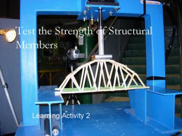
Test the Strength of Structural Members
- Learning Activity 2
2
Overview of Activity
- In this learning activity, we will test the
strengths of the cardboard structural members we
used in our model of the Grant Road Bridge. We
will design a series of experiments to determine
the strengths of these members in both tension
and compression. The experiments will be
conducted with a simple testing machine that uses
a lever to apply a controlled force to a test
specimen. - To analyze the experimental data obtained from
the testing machine, we will learn and apply the
principle of the lever. Finally, we will use a
computer spreadsheet to graph the results of our
tests. These graphs will help us to observe how
various physical properties affect the strength
of a structural member. We will also use these
graphs as a tool for analyzing and designing
bridges in Learning Activities 3 and 5.
3
Why??
- To design a structure, an engineer must be able
to determine the strengths of the structural
members that comprise it. In Learning Activity
1, we saw that external loads cause internal
forces to develop in a structure. We also
observed that a structure can successfully carry
its external loads only if the internal member
forces are less than the corresponding member
strengths. Thus an engineer cant evaluate the
load-carrying ability of the structure without
first being able to determine member strengths.
4
Lesson Objectives
- As a result of this learning activity, you will
be able to do the following - Calculate the cross-sectional area of a
structural member. - Describe the yielding, rupture, and buckling
failure modes. - Explain the factors that affect the tensile
strength and the compressive strength of a
structural member. - Design a testing program to determine the
strength of structural members. - Determine the tensile strength and the
compressive strength of structural members
through experimentation. - Explain the principle of the lever, and apply
this principle to the analysis of experimental
data. - Use a computer spreadsheet to analyze and graph
experimental data.
5
Cross Section and Cross Sectional Area
6
Cross-section and Cross-Sectional Area
- The cross-sectional area is the surface area of
the cross-section. For example, the
cross-sectional area of the solid bar on the
previous page is the area of the black rectangle.
To calculate it, you would multiply the width w
by the height h. The cross-sectional area is
always expressed in units of length squaredfor
example, square inches or square millimeters.
7
Tensile Strength
- In Learning Activity 1, we defined strength as
the maximum internal force a member can carry
before it fails. The internal force in a
structural member can be either tension or
compression. Because the failure of a structural
member in tension is very different from its
failure in compression, we must consider the
tensile strength and compressive strength
separately. - Tensile strength is the maximum tension force a
member can carry before it fails. As this
definition suggests, one way to determine the
tensile strength of a member is to load it in
tension until it failsthat is, pull on the
member from both ends until it physically breaks
in twothen measure the amount of force that
caused the failure.
8
Tensile Strength
- Suppose we wanted to test the tensile strength of
a carbon steel bar. Carbon steel is one of the
most common materials used in structures. It is a
mixture of iron and a very small amount of
carbonless than 1. For our carbon steel test
specimen, we will use the bar shown on the next
slide. It has a square cross-section measuring 1
inch on each side. This cross-section is
typically designated 1 x 1 (one inch by one
inch), and its cross-sectional area is 1 square
inch.
9
Tensile Strength
Steel is quite strong. To break a steel bareven
this relatively small onewe will need a special
machine like the one pictured below. This
hydraulic testing machine is capable
of stretching a test specimen with many thousands
of pounds. The machine can measure both the load
on the specimen and its corresponding
deformationthe increase in the length of the bar
as it is stretched.
10
Tensile Strength
To test the bar, we will clamp its ends into the
machine and gradually increase the load until the
steel fails. As the load is applied, the machine
will continuously measure and record both the
load and the deformation of the specimen. If we
plot these data on a graph, the result will look
something like this.
11
Tensile Strength
12
Tensile Strength
This graph is called a load-deformation curve. It
shows us how the member deformsand ultimately
how it failsas the load is increased. A careful
examination of the load-deformation curve will
tell us a lot about carbon steel. Lets examine
the curve from left to right. The
load-deformation curve originates in the lower
left-hand corner of the graph, which tells us
that the deformation is zero when the load is
zero. This certainly makes sense. The bar wont
start to stretch until we apply a force to it. As
we follow the curve up and to the right, we
notice that the curve is almost perfectly
straight from zero all the way up to about 36,000
pounds. The straight line means that the
deformation increases in direct proportion to the
load. For example, the deformation at 20,000
pounds is exactly twice as large as the
deformation at 10,000 pounds. In this linear part
of the load-deformation curve, the behavior of
the steel bar is said to be elastic. Elastic
behavior means that, if the load is removed, the
deformation will also return to zero. When a
member is elastic, it always returns to its
original length after it is unloaded. This
particular steel bar will remain elastic, as long
as the load on it is kept below 36,000 pounds.
When the load does reach 36,000 pounds, the
deformation of the bar is just over 1/100. The
total length of the bar has increased from 10 to
10.012a change of only about one tenth of one
percent.
13
Tensile Strength
As the load is increased beyond 36,000 pounds,
the behavior of the bar changes rather abruptly.
There is suddenly a huge increase in deformation,
with virtually no change in the load. The steel
is beginning to fail. When a material undergoes
large deformations with little change in load, it
is said to be yielding. The point on the
load-deformation curve where yielding begins is
called the yield point, and the force at which
yielding occurs is called the yield strength.
Beyond the yield point, the steel stretches like
taffy. And unlike the elastic behavior we
observed earlier, any deformation that occurs
beyond the yield point will not disappear after
the load is removed. This permanent elongation of
the member is called plastic deformation. Note
that, as the plastic deformation increases, the
bar eventually begins to carry more load. The
load peaks at 58,000 pounds, which is called the
ultimate strength of the member. After further
plastic deformation, the specimen finally breaks
into two pieces. This failure mode is called a
rupture.
14
Tensile Strength
So what is the tensile strength of this steel
member? Is it the yield strength or the ultimate
strength? Since the tensile strength is the force
at which the member fails, the answer to this
question depends on how the structural engineer
chooses to define failure. For most practical
structural applications, the engineer would
probably want to ensure that the member does not
yield. In such cases, failure would be defined
as yielding, and the tensile strength would be
36,000 poundsthe yield strength. In some cases,
however, the engineer might only want to ensure
that the member does not rupture. In such cases,
the tensile strength would be 58,000 poundsthe
ultimate strength. This latter definition of
failure might be appropriate, for example, when
the engineer is designing for the effect of an
extraordinary event like a major earthquake. In
such cases, the engineer might be willing to
accept some plastic deformation of the structure,
as long as it does not collapse.
15
Tensile Strength
This is an important and often misunderstood
pointin structural engineering, there is often
no single universally accepted definition of
failure. Rather, the engineer must exercise his
or her professional judgment to determine the
conditions under which a structure (or a
component of a structure) no longer will function
as intended. One other characteristic of the
load-deformation curve for the carbon steel bar
is worth mentioning. Note that, at rupture, the
bar has deformed two full inches20 of its
original length. This capacity to undergo very
large plastic deformation after yielding is
called ductility. Ductility is one of the most
beneficial properties of steel, and it is one of
the most important reasons why steel is so widely
used in structures. When a ductile member begins
to fail, its large plastic deformation provides
an obvious warning that something is wrong with
the structure. This warning provides an
opportunity to evacuate people and make emergency
repairs before the structure collapses. For this
reason, ductility greatly enhances structural
safety.
16
Tensile Strength
Not all structural materials are ductile.
Materials that do not undergo large plastic
deformation prior to failure are called brittle
materials. A typical load-deformation curve for a
brittle material is shown at right. Note that the
material ruptures without yielding and thus
without giving any warning that a failure
is about to occur. For this reason, brittle
materials are generally undesirable for
structural members. Cast iron is a brittle
material, which explains why cast iron has been
entirely replaced by steel in modern structures.
Concrete is a brittle material, which explains
(in part) why concrete is always reinforced with
steel bars when it is used as a structural
material.
17
Tensile Strength
18
Tensile Strength
We have seen how one particular structural member
made of one particular material can be tested to
determine its tensile strength. If we were to
repeat this test with many different
membersdifferent sizes, different
cross-sections, and different materialssome
patterns would begin to emerge. A careful
analysis of these patterns would reveal the
following facts about the tensile strength of
structural members
- Tensile strength depends on the cross-sectional
area of a member. As the cross-sectional area
increases, - the tensile strength increases in direct
proportion to the area. If the cross-section of
our carbon steel bar were changed from 1 x 1 to
2 x 2, the cross sectional area would increase
from 1 square inch to 4 square inches, and the
yield strength would increase from 36,000 pounds
to about 144,000 poundsfour times greater. - Tensile strength depends on the type of material
the member is made of. Every material has its own
characteristic strength, measured in units of
force per area (for example, pounds per square
inch or newtons per square meter). The yield
strength of carbon steel is 36,000 pounds per
square inch. Other types of steel - with yield strengths of 50,000 pounds per square
inch and higher are common. The tensile strength
of a member can be calculated by multiplying the
tensile strength of the material by the
cross-sectional area of the member. - Tensile strength does not depend on the length
of a member. If we used the same 1 x 1
cross-section but changed the length of our
specimen from 10 to 20, the tensile strength
would remain exactly the same. - Tensile strength does not depend on the shape of
the cross-section. If we tested a hollow tube or
circular rod with a cross-sectional area of 1
square inch, we would find that its tensile
strength is exactly the same as - the 1 x 1 square steel bar.
19
Compressive Strength
- Compressive strength is the maximum compression
force a member can carry before it fails. We can
determine the compressive strength of a
structural member by loading it in compression
until it fails, then measuring the amount of
force required to cause the failure.
20
Compressive Strength
- To understand how a structural member fails in
compression, try the following simple experiment.
Hold a yardstick or meter stick vertically, with
its bottom end on the floor. Now put the stick in
compression by pushing downward on its top end.
Gradually increase the compression force. At some
point, the stick will suddenly bend sidewaysin
engineering terms, it will buckle. Buckling is a
failure that occurs when compression causes a
member to suddenly bend sideways, perpendicular
to the direction of the applied load. Buckling is
the most common failure mode for structural
members in compression. When a member fails by
buckling, its compressive strength is the
internal force at which buckling occurs. - Try repeating the same experiment with a 12-inch
wooden ruler. Unless youre really strong, youll
probably find that you cant push hard enough on
the 12-inch ruler to make it buckle. This
observation suggests an important characteristic
of buckling failures Shorter members have
greater compressive strength than longer ones.
21
Compressive Strength
This graph vividly illustrates the effect of
member length on compressive strength. Note that
an 80 member is less than one-tenth as strong as
a 10 member, even though their cross-sections
are identical.
22
Compressive Strength
- How do the size and shape of the cross-section
affect compressive strength? In Learning Activity
1, we observed that hollow tubes seem to be more
effective than solid bars at carrying
compression. Lets test that observation now with
another simple experiment. Using the same
file-folder cardboard you used to build the Grant
Road Bridge, cut out two identical rectangles
measuring 5 centimeters wide and 10 centimeters
long. Fold one of the two rectangles into a
square tube measuring 1cm x 1cm. Glue the edges
together as we did when we prefabricated the
square tubes in Learning Activity 1. The second
rectangle should remain unfoldeda 5cm-wide bar
with a length of 10cm. We now have two structural
membersa bar and a tube. Both are the same
length, and both use exactly the same amount of
material. Place each one with its ends between
your thumb and forefinger, and squeeze. Youll
find that the flat rectangular bar buckles with
only the slightest compressive force. On the
other hand, the tube is amazingly strongalmost
impossible to buckle with one hand. This simple
test clearly demonstrates another important
characteristic of buckling failures A hollow
tube has significantly higher compressive
strength than a solid bar using the same amount
of material.
23
Compressive Strength
24
Compressive Strength
25
Compressive Strength
26
Compressive Strength
27
The Principle of a Lever
- When actual structural members are tested in a
laboratory, powerful hydraulic machines are used
to perform the tests. We dont have hydraulic
power available for this project, but we do have
the power of the lever to help us apply a large,
controlled, measurable tension or compression
force to a cardboard structural member. The
simple testing machine we will use in this
learning activity is based on the principle of
the lever thus, to understand how the machine
works, you will need to understand how a lever
works.
28
The Principle of a Lever
- Suppose you are doing a landscaping project, and
you encounter a 200-pound rock that must be
moved. The only tools available are a 6-foot
long steel pipe and a short log. How can you move
the rock? As the picture suggests, you can move
the rock quite easily by using the steel pipe as
a lever and the log as a fulcrum. A lever is a
simple machine, consisting of a bar or rod that
rotates on a pivot. The pivot is called a
fulcrum. When you apply a downward force to one
end of the lever, the lever pivots on the fulcrum
and applies an upward force to the rock at the
other end.
29
The Principle of a Lever
30
The Principle of a Lever
31
The Principle of a Lever
- In our example, we know that the weight of the
rock, F1 , is 200 pounds. Lets place the log
(the fulcrum) one foot away from the rock. Since
the steel pipe (the lever) is six feet long, then
L1 is 1 and L2 is 5. What force do you need to
apply to the long end of the lever to lift the
rock? If you substitute the known values of L1 ,
L2 , and F1 into the equation above, and solve
for F2 , you will find that you can lift the
200-pound rock with a force of only 40 pounds.
32
Converting Mass to Weight
- Weight is a force thus, we express the weight of
an object in units of force. In the lever example
above, the weight of the rock and the forces
applied to the lever are expressed in poundsthe
standard measure of force in the U.S. Customary
system of units. - The experiments conducted in this learning
activity use metric units, also called SI units.
(SI stands for Systeme International.)
Determining the weight of an object in SI units
is a bit more complicated than doing it in U.S.
units. When you weigh an object on a metric
scale, the number you read from the scale is
usually in grams or kilograms, which are units of
mass, not force. Thus, when you weigh an object
on a metric scale, you actually do not measure
its weight. You measure its mass.
33
Converting Weight to Mass
- To determine the weight of this object, you must
convert its mass to a force, using the equation
In this equation, W is the weight of the object,
m is its mass, and g is the acceleration of
gravity. In SI units, g 9.81 meters/sec2. If
you express the mass m in kilograms, then the
weight W will be in newtons.
34
The Problem
- The Need
- The Town Engineer of Hauptville, New York, has
decided to conduct a structural evaluation of the
Grant Road Bridge, to ensure that it can safely
carry the required highway loads. Before he can
begin analyzing the structure, he will need to
obtain information about the strengths of the
various structural members used in the main
trusses. He decides to hire a materials testing
laboratory to design and conduct an experimental
testing program to provide the necessary
information.
35
The Problem
- The Need
- The Town Engineer of Hauptville, New York, has
decided to conduct a structural evaluation of the
Grant Road Bridge, to ensure that it can safely
carry the required highway loads. Before he can
begin analyzing the structure, he will need to
obtain information about the strengths of the
various structural members used in the main
trusses. He decides to hire a materials testing
laboratory to design and conduct an experimental
testing program to provide the necessary
information.
36
The Problem
- Your Job
- Your materials testing company, Universal
Structural Materials Assessment, Inc., has been
hired by the Hauptville Town Engineer to provide
experimental data in support of his structural
evaluation of the Grant Road Bridge. Your job is
to design and conduct a program of
experimentation to determine the strengths of all
structural members used in the main trusses of
the bridge. As a technical specialist, you are
responsible for providing your client with
complete, accurate data and presenting that data
in a manner that is both understandable and
usable.
37
The Solution
- The Plan
- Our plan to provide the Hauptville Engineer with
the information he needs is as follows - Familiarize with the testing machine that we will
use for our experiments. - Design a testing program.
- Make the test specimens.
- Conduct tension and compression strength tests.
- Analyze and graph the experimental data.
- The product of our work will be a series of
graphs that the Hauptville Engineer can use as
the basis for his structural evaluation.
38
How the Testing Machine Works
When you test the tensile strength of a cardboard
structural member, you will clamp the top of the
test specimen to the loading arm at the T-Line.
The bottom of the specimen will be clamped to the
base. You will hang the plastic bucket from the
notch at the end of the loading arm, then slowly
fill it with sand until the specimen ruptures.
After the failure, you will weigh the bucket and
sand, and apply the principle of the lever to
determine the internal force in the specimen at
the instant of failure. The principle of the
lever says that
39
How the Testing Machine Works
40
How the Testing Machine Works
41
Design The Testing Program
- Now that the testing machine is ready to go, you
are probably anxious to start doing some
experiments. But before we can start testing, we
first need to design the testing program. The
objectives of this planning process are to - Ensure that we get accurate data
- Ensure that we get the right kinds of data to
support the projects we will be doing later and - Ensure that we do not waste time or material by
doing unnecessary tests.
42
Design The Testing Program
- To accomplish these objectives, we must apply
some of the observations we made earlier about
the tensile strength and compressive strength of
structural members. Specifically, we need to look
at each of the factors on which the tensile and
compressive strength depend, and vary these
factors systematically in our tests. As a
minimum, the range of values for each factor must
be adequate to analyze every member in the Grant
Road Bridge. The logical thought process leading
to the design of our testing program is as
follows - Tensile strength depends on the cross-sectional
area of a member. Therefore, we must create test
specimens with a variety of different
cross-sectional areas. The cross-sectional area
of a rectangular member is simply its width times
its thickness. Since all of our specimens will
have the same thickness (the thickness of the
cardboard), we need to create test specimens with
a variety of different widths. - Tensile strength does not depend on the length of
a member. Therefore, all of our tension test
specimens can be the same length. We will use 20
centimeters, because this length fits the testing
machine nicely. - Tensile strength does not depend on the shape of
the cross-section. Therefore, all of our tension
test specimens can have the same type of
cross-section. We will use a simple rectangular
bar.
43
Design The Testing Program
- Compressive strength depends of the shape and
size of the cross-section. Therefore, we must
create compression test specimens for each of the
different cross-sections we plan to use in our
structure. We will test rectangular tubes with
the same dimensions as the tubes used in the
Grant Road Bridge model. - Compressive strength depends of the length of the
member. Therefore, we must create test specimens
with the full range of different lengths we plan
to use in our structure. We will use lengths from
5 to 16 centimeters. - Tensile and compressive strength both depend on
the material the member is made of. Therefore, to
do a truly comprehensive testing program, we
would need to create test specimens of various
different materials. Since our projects will all
use the same type of cardboard, however, we will
only test this one material.
44
Design The Testing Program
- In designing the testing program, we must also
consider the effects of experimental error and
the natural variability of the properties we are
attempting to measure. There are many possible
sources of experimental error in our test setup.
(We will discuss them in detail later.) Some of
these can be controlled by conducting the tests
very carefully but no matter how careful we are,
our experimental data will exhibit some natural
variability. For this reason, we should repeat
each of our experiments several times and average
the results. Repeating each experiment several
times is especially important for the compression
tests, which are inherently more variable than
the tension tests.
45
Design The Testing Program
46
Make the Test Specimens
- Using the notebook, make your complete set of
test specimens to be used in conducting our
experiments. - Analyze and graph the tension data
- Create a graph of tensile strength vs. member
width - Test compression specimens
- Analyze and graph the compression data
- Create a graph of compression strength vs. member
length
47
By the way.
- Answer all ten Questions for Learning Activity 2
- Good Luck
Recommended
