
EARTH STATION ANTENNAS - PowerPoint PPT Presentation
1 / 87
Title:
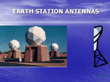
EARTH STATION ANTENNAS
Description:
An antenna with a feed in the center of the paraboloid (axisymmetric) represents ... Corrugated Conical Horn. L.A.F.S. Comunicaciones Satelitales. FEEDER'S. L.A.F.S ... – PowerPoint PPT presentation
Number of Views:2694
Avg rating:5.0/5.0
Title: EARTH STATION ANTENNAS
1
EARTH STATION ANTENNAS
2
Antenna Configurations
- An antenna with a feed in the center of the
paraboloid (axisymmetric) represents the simplest
antenna configuration that is potentially capable
of meeting the RF specifications for Earth
station applications. A major advantage of such a
configuration is that mechanically, it is
relatively simple, reasonably compact and, in
general, fairly inexpensive.
3
Dish Antennas Geometry
Satellite Earth stations use dish antennas of
0.5 - 30 meters in diameter. The dish surface
contour is based on the equation for a
parabola y2 4fx where f, is the focal
length, and x, is the coordinate along the axis
of the paraboloid.
4
Dish Antennas Geometry
A paraboloidal surface contour satisfies the
requirement that all the energy radiated from a
launcher at the focal point towards the surface
will be reflected to form a phase coherent plane
wavefront across the dish aperture. Expressed
in another way, path lengths ABC, ADE, and AFG,
are all equal.
5
Dish Antennas Geometry
Geometry of a Paraboloid
6
Focal Length to Antenna Diameter ratio, F/D
7
Antenna Configurations
- Four reflector antenna configurations are
commonly employed for earth station applications,
namely - Prime Focus Axisymmetric Prime focus
- Axisymmetric Dual Reflector Cassegrain
- Single offset Offset feed
- Dual offset
8
Antenna Configurations
- Center Feed Antennas
- Simplest form of axisymmetrical configuration is
a paraboloidal reflector with a primary feedhorn
located at the focus. - However, this leads to a long waveguide-run
between the feed and the electronics box for
antennas whose diameter is greater than about 3
meters. This is undesirable because it leads to
reduction in signal power, and increase in noise.
9
Center Feed Antenna
10
Antenna Configurations
- Center Feed Antennas
- A more compact configuration, especially for
larger antenna diameters, can be realized by the - introduction of a subreflector. The feedhorn is
located at the rear of the main reflector,
eliminating the need for long, potentially lossy, - waveguide runs.
- This is known as Cassegrain antenna.
11
Basic Geometry of a Cassegrain Antenna
12
Offset Feed Antennas
The offset feed antennas, such as the offset
Cassegrain and Gregorian, achieve a better
radiation pattern because of lower aperture
blockage. They are often known as nonsymmetrical
antennas, and are generally used in small Earth
stations because of construction problems and
higher cost.
13
Common Antenna Feed Systems
14
Other Feed Systems
15
Single Offset
16
Dual Offset
Dual reflector axisymmetric
17
ANTENNA CONFIGURATIONS AND RANGES OF TYPICAL
DIAMETERS ANTENNA CONFIGURATION TYPICAL RANGE
OF DIAMETERS (m) Prime focus
axisymmetric 0.6 - 7.0 Dual reflector
axisymmetric 2.0 - 32.0 Single Offset 0.6
- 3.6 Dual Offset 0.6 - 8.0
18
ANTENNA CONFIGURATIONS
- The performance of dual reflector antennas, both
sym-metrical and offset, is to a large extent
determined by the illumination distribution in
the main reflector aperture. Control over this
parameter can be achieved by shaping the
reflector profiles using either geometrical
optics or diffraction techniques. These
techniques have been applied to earth station
antennas, especially large INTELSAT Standard As
to increase the gain in the receive mode.
19
ANTENNA CONFIGURATIONS
- The greatest use of the offset geometry has been
made at Ku-band. For smaller diameters,
typically less than 2m, the single offset antenna
has been favored. In general, the projected
aperture periphery has been circular, however,
new designs involving a diamond/hexagonal
periphery have been introduced which provide
about 0.5dB more gain than the conventional
design together with very low sidelobe radiation
in the principal azimuth plane. - Dual reflector designs have involved both
circular, hexagonal and elliptical projected
apertures.
20
ANTENNA CONFIGURATIONS
- The latter has been utilized to improve
performance for large diameters and to provide a
faster rate-of-fall-off of sidelobe radiation
with absolute angle from boresight in critical
azimuth planes. Such a system requires shaping
both the profiles of the main and sub-reflectors.
The Gregorian geometry has been utilized for all
dual reflector designs. Sidelobe radiation with
all sidelobes below 29-25 log? dBi is realized
for each antenna, combined with efficiencies in
the region of 69 in the received band and 66 in
the transmit.
21
BASIC ADVANTAGES AND DISADVANTAGES OF SINGLE AND
DUAL AXI-SMMETRIC REFLECTOR ANTENNAS -----------
--------------------------------------------------
--------------------------------------------------
------ CONFIGURATION ADVANTAGES
DISADVANTAGES Single
1. Inexpensive 1. Comparatively heavy and
inaccessible feed requiring
support. 2. Reasonable side-
2. Blockage for small aperture
lobe performance blockage due to
primary feed/support
structure/waveguide runs. 3. Moderate
efficiency 3. Long waveguide runs to feed
with loss associated I2R losses.
4. Cross polarization 4. Not
a compact mechanical structure for
diameters greater than 2m.
5. Mostly employed for receive-only
application.
22
BASIC ADVANTAGES AND DISADVANTAGES OF SINGLE AND
DUAL AXI-SMMETRIC REFLECTOR ANTENNAS -----------
--------------------------------------------------
--------------------------------------------------
------ CONFIGURATION ADVANTAGES
DISADVANTAGES Dual 1.
Convenient feed 1.More expensive due to need
(e.g. cassegrain)
location with inputs/out- for subreflector
and larger
puts within hub. Feedhorn.
2. Compact structure 2.
Sidelobe performance de- graded by feed
spillover and diffraction past
subreflector. 3. Moderate efficiency 3.
Efficiency reduced by aperture blockage
caused by subreflector 4.
Cross-polarization 4. Really
limited to hub applications with
reflector sizes Dgt100, since achieving
adequate sidelobe performance is
difficult.
23
BASIC ADVANTAGES AND DISADVANTAGES OF SINGLE AND
DUAL AXI-SMMETRIC REFLECTOR ANTENNAS -----------
--------------------------------------------------
--------------------------------------------------
------ CONFIGURATION ADVANTAGES
DISADVANTAGES 1. Single
offset 1. Inexpensive minimum 1.
Significant depolarization number of
parts. performance due to
asymmetric geometry for linear
polarization. 2. No
aperture blockage, 2. Relatively inaccessible
and hence improved efficiency
inconvenient position of primary and
sidelobe performance. Feed mounted at end
of long feed arm. 3. Ease
of installation. 3. Accommodation aspects
of electronics boxes difficult
along feed arm. 4. Application
generally 4. Load carrying capacity of
feed reserved for VSAT usage. Arm
causing potential distortion of
reflector physical shape.
24
BASIC ADVANTAGES AND DISADVANTAGES OF SINGLE AND
DUAL AXI-SMMETRIC REFLECTOR ANTENNAS -----------
--------------------------------------------------
--------------------------------------------------
------ CONFIGURATION ADVANTAGES
DISADVANTAGES Dual
offset 1. No aperture blockage, hence 1.
Slightly more expensive due to
improved efficiency.
better performance. With shaping
efficiencies of 84. 2. High polarization
purity. 3. Convenient accommodation
aspects for mounting various electronics
boxes SSPAs (redundant), power supply
and switching units. 4. Load carrying
capacity for electronics boxes along feed
arm. 5. Accessibility to primary-feed and
electronics in operation. 6. Application for
VSAT and, or HUBs.
25
Antenna Mounts
An Earth station antenna typically requires a
rigid steel backup structure combined with an
accurate dish surface. They are fitted with
necessary bearings, gears, and drives to enable
pointing accuracy within a few tenths of a
degree. The structure must also be able to
withstand extreme weather conditions, from
excessive heat to cold, and hurricanes.
26
Antenna Mounts
Three common antenna mount types are XY
mount, AZ/EL mount, and polar mount.
27
Antenna Mounts
X-Y mount This mount is used for medium-sized
antennas. In this mount, the lower axis (X) is
parallel to the ground. Rotation about this axis
moves the antenna in elevation. The upper axis
(Y) lies in a vertical plane, and is
perpendicular to the X-axis. The position of the
Y-axis in the vertical plane depends on the
rotation of the X-axis, and can range from
vertical to horizontal.
28
Antenna Mounts
X - Y Mount
29
Antenna Mounts
AZ/EL mount The location of a point on Earth
can be described by using the azimuth-over-elevati
on coordinate system. Azimuth is defined as an
angle produced by rotation about an axis, which
is perpendicular to the local horizontal plane.
The elevation axis rotates in the local
horizontal plane as the azimuth angle rotates.
30
Antenna Mounts
AZ/EL Mount
31
Antenna Mounts
Polar Mount A polar mount has two axes of
rotation. The first one is the hour angle axis,
which is parallel to the Earth's axis. It is
inclined in the north-south direction from the
local horizontal through an angle equal to the
latitude of the site. Therefore, the hour angle
axis is parallel to the ground at the equator and
perpendicular to the ground at either the North
or the South Pole.
32
Antenna Mounts
Polar Mount
33
Basic Antenna Definitions
- Transmitting antenna does not radiate uniformly
in all angular directions, nor does a receiving
antenna detect energy uniformly from all
directions. - Directional selectivity characterized by its
radiation pattern. The pattern is a plot of
relative strength of radiated field, amplitude
and phase, as a function of the angular, ? and Ø,
of a spherical co-ordinate system for a constant
radius r. The amplitude of this pattern is most
important and can be expressed as a relative
power, or field pattern on a logarithmic decibel
pattern with a maximum of 0dB.
34
Radiation pattern
- typically comprises a main beam and a sidelobe
structure which is depicted as a two-dimensional
cartesian plot. - - As the antenna dimension increases, the width
of the main beam decreases, and periodicity of
the sidelobe region increases.
35
Main beam / sidelobe region
- the peak of the main beam represents the
highest level of field strength and approximately
70 of the radiated energy is enclosed. - The sidelobe region represents a potential source
of interference into the communication link, and
for this reason is generally required to be of
low level.
36
Antenna Radiation Pattern Plot
37
Antenna half-power beam width
- The angular width of main beam of the antenna
radiation pattern is characterized by the
half-power beam width (HPBW). This is defined as
the full angular width between the two points
which are 3dB below the main beam peak.
38
Gain, directivity and efficiency
- Gain and directivity are quantities which define
the ability to concentrate energy in a particular
direction and are directly related to the antenna
radiation pattern. It includes all ohmic and
dissipative losses arising from conductivity of
metal and dielectric loss.
39
Basic Antenna Definitions
- The gain value corresponds to the peak of the
main beam of the radiation pattern which is
referred to the antenna boresight direction. - The antenna efficiency factor, ?, is always less
than unity and is more often expressed as a
percentage.
40
Antenna noise temperature
- In sat-coms, the noise caused by the thermal loss
of the ground and atmosphere is received by the
sidelobes of the antenna and degrades the overall
receive band performance of the antenna.
41
Polarization and cross-polarization
- Both the antenna and the electromagnetic field
received or transmitted have polarization
properties. The polarization of em wave
describes the shape and orientation of the locus
of the extremities of the field vectors as a
function of time. A wave may be described as
linearly polarized, circularly polarized, or,
elliptically polarized.
42
Linear polarization
- Is such that the E-field, electric field, is
orientated at a constant angle as it is
propagated. The angle may be arbitrary, (slant),
but often for convenience is defined to be either
vertical or horizontal. Circular polarization is
the super position of two orthogonal linear
polarizations, for example vertical and
horizontal, having equal amplitude and with a 90º
phase difference. The tip of the resultant
E-field vector may be imagined to rotate as it
propagates a helical path.
43
Linear polarization
44
Circular Polarization
- A clockwise rotation viewed as the wave
propagates away from the observer is referred to
as right hand circular polarization and an
anti-clockwise rotation as left-hand circular
polarization.
45
Circular Polarization
46
Cross polarization
- This is of constant interest to satellite
communication antenna designers. - In the case of an antenna transmitting, or
receiving, a linearly polarized field, the
cross-polar component of the field is a right
angle to the co-polar component. E.g., if the
co-polar component is vertical, then the
cross-polarized component is horizontal.
47
Circular cross-polarization
- Is that of the opposite hand to the desired
principal, or reference polarization. Impure
circular polarization is, in fact, elliptical.
The level of impurity is measured by the
ellipticity and known as the axial ratio.
48
CARTESIAN PLOT OF ANTENNA RADIATION PATTERN
49
POLARIZATION DISCRIMINATION IN AN ANTENNA
RADIATION PATTERN
50
Antenna Parameters
The important parameters of an antenna are
Gain, Beamwidth, and Sidelobes.
51
Antenna Gain
Antenna gain is defined as follows When a radio
wave arriving from a distant source impinges on
the antenna, the antenna "collects" the power
contained in its "effective aperture" (Ae). If
the antenna were perfect and lossless, the
effective aperture area Ae would be equal to the
actual projected area A. For a circular
aperture, the projected aperture is Apd²/4
52
Antenna Gain
Taking into account losses and the nonuniformity
of the illumination law of the aperture, the
effective area is in practice Ae ?A Ae
?p(d/2)2 (1.) where ? antenna efficiency and
? lt 1.
53
Antenna Efficiency
Antenna efficiency is affected by a) The
subreflector and supporting structure
blockage. b) The main reflector rms surface
deviation. c) Illumination efficiency, which
accounts for the nonuniformity of the
illumination, phase distribution across the
antenna surface, and power radiated in the
sidelobes. d) The power that is radiated in the
sidelobes.
54
Antenna Gain
Then, the on-axis antenna power gain (relative to
an isotropic radiator) is given by G
4pAe/?² (2.) where ? is the free space
wavelength p 3.14159.... Ae effective
aperture of the antenna Substituting for Ae in
(2.) yields G ?(pd/?)² (3.)
55
Antenna Gain
Expressed in decibels GdBi 10 log ? 20 log
p 20 log d - (20 log ?) Or GdBi 10 log ?
20 log f 20 log d 20.4 dB Where ?
antenna efficiency d antenna diameter in
meters f operating frequency in GHz
56
Antenna Gain
Antenna Gain is a function of both frequency
and dish diameter Gain 10 Log(60.7 f2d2)
dB at 55 antenna efficiency f operating
frequency in GHzd antenna diameter in meters
57
Antenna Beamwidth
Beamwidth is a measure of the angle over which
most of the gain occurs. It is typically defined
with respect to the Half-Power Beamwidth (HPBW)
or 3 dB points of the main lobe in the antenna
radiation pattern. It is given
by Where ? the antenna
efficiency d the antenna diameter
in meters ? the wavelength, c/f
58
Antenna Radiation Pattern
59
Antenna Sidelobes
While most of the power radiated by an antenna
is contained in the main lobe", a certain amount
of power can be transmitted, (or received), in
off-axis directions. Sidelobes are an intrinsic
property of antenna radiation and cannot be
completely eliminated. However, sidelobes are
also due to antenna defects that can be minimized
with proper design.
60
Antenna Figure of Merit
Antenna Figure of Merit is described in terms of
G/T in dB/K G refers to the antenna receive
gain in dB T refers to receive system noise
temperature in Kelvin Typical values Std A 35
dB/K Std B 31.7 dB/K
61
Antenna Figure of Merit G/T
G/T defines how good the system is G/T Ant.
Gain dB - 10 Log Tsystem Tsystem Tant/(L
(1-1/L)To Te)
62
Antenna Gain vs. Diameter
63
Antenna Temperature
64
Antenna Standards
- ITU-R Record 580-1, Module 1, defines the desired
sidelobe envelope for different types of
antennas. - They are
- Antennas installed after 1988 and with a ratio of
- d/? gt 150, must meet the following
characteristics - G 29 - 25 log Q dBi
- Where Q is degrees from boresight and 1 lt Q lt
20 - d is the antenna diameter (meters)
- ? is the wavelength for the operation frequency
(meters)
65
Antenna Standards
ITU-R Record 580-1, Module 1, defines the desired
sidelobe envelope for different types of
antennas. B) For smaller antennas with d/?
between 35 to 100 (1.75m to 5m, for C-band and
75cm to 2.1 m, for Ku-band) G 52 - 10 log d/?
- 25 log Q dBi for (100?/d) lt Q lt d/5?
66
Antenna Radiation Diagram and Beamwidth
67
Antenna Bandwidth
Dish antennas are wideband devices. As seen
from the gain equation, for a given diameter, the
gain of a dish will increase as the frequency of
operation increases. However, operation away from
the design frequency will normally result in
impaired performance due to the limitations of
the feed/launch system.
68
Earth Station Antenna
- Satellite Location
- Visibility Angles
- Azimuth,
- Elevation
69
Visibility Angles
70
Visibility Angles
71
Visibility Angles
72
Visibility Angles
73
Antenna Standards
Since 1965, various antenna standards have been
approved for use within the INTELSAT system.
These standards are classified by the following
basic parameters 1. Dish Diameter 2. Frequency
of Operation in the RF Spectrum 3. Figure of
Merit (Gain/System Noise Temperature) 4. Mode of
Operation
74
Antenna Standard A
This is commonly known as a "Large Dish" Earth
station and has been in use since 1965 (INTELSAT
I - "Early Bird"). In recent years a revised
Standard A specification has been introduced to
take advantage of the higher power available from
the new generation satellites.
75
Large Dish
76
Standard A
1.Dish diameter for the Standard A was about 30
meters per the revised specification, it is
about 13-20 meters. 2. It operates in the 6/4
GHz band, but it can be retrofitted, in some
cases, to operate in the 11/14 GHz band. 3. For
the old standard A, the Figure of Merit was 40.7
dB/K. It is 35 dB/K per the revised
specification. This standard can be used for
all services.
77
Standard B
This type of Earth station was initially
introduced as a more economical alternative to
the standard A for use on Thin Route systems
with low traffic capacity requirements. This
standard can be now used for all services.
78
Standard C
With the advent of the INTELSAT V satellites,
which operate in Kuas well as C-band, this
standard was introduced. In recent years this
specification has also been upgraded. These
stations can be equipped to operate any of the
services available in the Ku-band. They can
operate with any other station utilizing the Ku-
band, and with C-band stations via
cross-connected transponders.
79
Antenna Standards
Standard D This standard has been
discontinued. Standard E This standard was
introduced initially for use on the INTELSAT
Business Service (IBS) operating in Ku-band. The
two larger dishes in this standard are authorized
for use in the Intermediate Data Rate (IDR)
services as well. The choice of station depends
on the user's requirements. Standard F As with
the Standard E, this standard was initially
designed for use with IBS but has since been
authorized for use with IDR
80
Antenna Standards
Standard G This standard was introduced for
those international carriers whose Earth stations
do not conform to any of the above standards.
They can operate in either C- or Ku-band. There
are no specific antenna sizes, figures of merit,
or modulation methods, but they must conform to
mandatory requirements, such as sidelobe gain,
etc. Standard H This standard has been
introduced to provide the INTELSAT DAMA service
in the 6/4 GHz band. Standard K This standard
is intended for the INTELSAT VSAT Business
Service operating in the 14/11 GHz and/or
14/12 GHz bands.
81
High Power Amplifiers
- TWT Power Amplifiers
- Klystron Power Amplifiers
- Solid State Power Amplifiers
82
HPA Backoff
- Amplitude and phase characteristics
- Non-linearity of amplifiers
- Backoff levels
83
Low Noise Amplifier
- LNA (Low Noise Amplifier)
- Located close to the antenna
- Produces very little electronic noise
- LNB (Low Noise Blockconverter)
- Amplifies and converts the RF carrier
into a lower range of frequencies
84
FEEDERS
Dual Feeder/Dual Band
Single Feeder/Dual Band Polarotor
85
FEEDERS
Corrugated Conical Horn
86
FEEDERS
87
FEEDERS
Polarotor
Dual Band Feeder
Recommended
CrystalGraphics Presentations


