
General Arrangement Drawings: Three-View - PowerPoint PPT Presentation
1 / 12
Title:
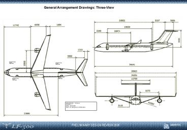
General Arrangement Drawings: Three-View
Description:
Minimal yaw effects during engine out scenario ... Empennage: CFRP. PRELIMINARY DESIGN REVIEW 2006. LF-300. University of. BRISTOL ... – PowerPoint PPT presentation
Number of Views:773
Avg rating:3.0/5.0
Title: General Arrangement Drawings: Three-View
1
General Arrangement Drawings Three-View
ENTRANCE DOOR 72X32 TYPE 1 EXIT
ENTRANCE DOOR 72X32 TYPE 1 EXIT
ENTRANCE DOOR 72X32 TYPE 1 EXIT
ENTRANCE DOOR 72X32 TYPE 1 EXIT
DESIGNED BY H.Grewal EDITION 1 DATE
28/11/2006 NOTE All Dimensions in Millimetres
2
Cabin Layout
US Cabin 2-Class
EU Cabin 1-Class
US Cabin 1- Class
Cabin Cross-Section
3
- Preliminary Selection
- Develop concepts
- Define criteria
- Choose datum
- Compare Concepts
- Scenario analysis
- Reality check
- Soft
- Data
- Manufacturers
- Production Rates
- Commonality
- Selection
- Develop
- concepts
- Define attribute
- a) Scales
- b) Importance
- Rate concepts
- Reality check
Morphology Selection
- Hard
- Data
Final Concept
4
Rear Engine
A319
- Minimal yaw effects during engine out scenario
- Higher probability of destroying second engine in
fan burst - Scaling issues for High Bypass ratio engines
- Standard configuration with latest technology
installed - High use of composites and more-electric
technology to reduce weight - Proven, relatively low-risk option
Larger Fuselage with 1.5x aisle width
Large, heavy tail structure
Supercritical wings increase TO/L performance and
reduce weight
Reduction in landing gear length and weight due
to no under wing engines
Aerodynamically efficient, Clean wings
Modern engines with latest fuel and noise
efficiencies
High Wing
Strut-Braced
High wing and external undercarriage leaves clear
through-aircraft cargo bay
- Engines mounted further out on wing for inertia
relief - Scope for reducing engine size as less thrust
needed
Large tail fin to counteract engine out
T-tail removes control surfaces from turbulent
jet-wash flow
Telescopic mechanism negates compressive loads
Winglets effectively increase span
Internal stairs and low sill height reduce
infrastructure requirements and improve
turnaround time
High aspect ratio leads to improved laminar flow
Reduced wing weight and improved aerodynamics
increase fuel efficiency
Low ground clearance leads to large reduction in
landing gear weight
5
- Turn Around
- Reduction in passenger/cargo transition times due
to lower sill height and internal stairs - Wing Box removed from the cargo area giving
potential for continual cargo load/unload system
potential to halve cargo loading, shown to be a
dominant factor in turn around time for the
737-700
- Aerodynamic Efficiency
- Assuming approximately the same wing area,
increased span increases Aspect Ratio which
combined with an increased efficiency factor e
due to a high wing position gives increased L/D
using the simple equation of - Cd Cdo kCl2 as k 1/pi AR e
- Wave drag assumed neutral due to t/c reduction
- Taper Ratio of 0.3 keeps near elliptical lift
distribution - Current Cruise L/D for 3000nm is 19 (assuming 74
A319 OWE)
- Structural Efficiency
- Increased span and reduced t/c without weight
penalty - Predicted weight reduction due to smaller t/c,
despite increase in aspect ratio - Combined weight of wing and strut accounts for
same percentage of OWE as cantilever, so there is
an overall weight reduction
- Fuel Efficiency
- Current predictions show 24 reduction in fuel
burn for 3000 nm mission at 74 A319 OWE - With projected fuel price increase, without
including the very probable introduction of
aviation fuel tax, fuel burn becomes dominant in
DOC costing and significant savings are to be
made in this area
- Undercarriage
- Engine ground clearance is not a problem so
fuselage can be low with a shorter, lighter
undercarriage - Undercarriage typically accounts for
approximately 10 of OWE
- Composite Technologies
- Use of composites contributes to 20 OWE
reduction target - Limited self-heal after damage. The composite
contains a layer of uncured resin filled hollow
glass fibre, which breaks and releases the resin
to the damaged region.
6
- Drag Penalty
- Assumed t/c reduction leads to wave-drag
neutrality for Loop Zero sizing - Increase in wetted area due to strut scaled into
Loop Zero sizing - Problems involved in strut-wing integration
- Torsional Stiffness/Strength
- A solution would be to offset as shown, but
this will lead to increased bending moments,
structure and weight
Risk Analysis
Landing Inertial Loads
Key
- Engines approximately twice as far out compared
to conventional aircraft - 6 predicted increase in span compared to
conventional - Strut only operative in tension due to poor
- resistance to compression achieved by use of a
damped telescopic sleeve - Critical load in landing as wings remain
unsupported throughout
A Support strut has uncontrollable dynamic effects
B Engine out yaw performance unmanageable
C High Aspect ratio expected is unachievable
D Projected weight savings not realised
E Designing, manufacturing and certifying telescopic strut
- Ditching
- Sill heights must pass certification
7
Structures Materials
Aerodynamics
Risk Matrix
Propulsion
8
- Low ground clearance low sill height allow
self-contained stairs - Market research showed only 1 galley required for
1 class - 1.5 sized aisle use of 2 doors allow 2x entry
egress rates - Cinema seats and 1.5 aisle allow for reduced
cleaning time - Novel single cargo bay allows simultaneous
loading/unloading - Fuel options (3000nm assumed)
- 2 x fuel trucks (IOC increase)
- New legislation to allow fuelling whilst pax. on
board (?)
33mins
20mins
13 min reduction in critical path Low Wing
allows 5min reduction
Key Design Driver -13mins Reduction
9
Cabin Pressure/Air Conditioning
Leads to non-pneumatic aircraft Reduced weight Lowers maintenance costs More reliable More accurate monitoring of system
Systems Comparison
LF-300 A319 B737
Cabin Pressure Electric Pneumatic and Electric Pneumatic and Electric
(TBD) Landing Gear Electric Braking System/ Hydraulic back-up Hydraulic System Hydraulic System
Engines (TBD) Electro Thermal/ Electro Expulsive Bleed Air Bleed Air
Fuel System (TBD) All Electrical Pump Hydraulic/ Pneumatic Pump Hydraulic/ Pneumatic Pump
Ice/Rain Protection Electro Thermal/ Electro Expulsive Bleed Air Bleed Air
Power Distribution 1 Electric 2 Electric 3 Hydraulic 1.Hydraulic 2.Hydraulic 3.Hydraulic 1.Hydraulic 2.Hydraulic 3.Hydraulic
Power Distribution Power Distribution
Power on Demand lower power consumption Reduced weight Better reliability Improved maintenance Experience proven safety in form of a back-up hydraulics system Power on Demand lower power consumption Reduced weight Better reliability Improved maintenance Experience proven safety in form of a back-up hydraulics system
A Significance of change in power consumption B Better reliability C Improvement in maintenance D Significance of weight reduction
10
Lights
High-intensity Discharge (HID) and Light Emitting
Diodes (LED) take over lighting both the interior
(Cockpit, Cabin) and the exterior of the aircraft
(Anti-collision, Navigation etc.)
10-fold increase in in-service life Improved
maintenance Reduced Power Consumption
Avionics
Aircraft functions reside as software on a common
processing unit. The system is open architecture
to allow third party subcontractors to integrate
their functions.
Large reduction in architecture complexity Large
Scale integration of aircraft functions Lower
power consumption Reduced weight Better
reliability Improved failure identification/locali
sation More efficient use of aircraft sensors
LF300 A319 B737
Avionics CSS Federated Federated
Lights HID and LED Filament/ Halogen Filament/ Halogen
Systems Comparison
11
- Competitors
- Include Boeing 737 and A319
- A319 is the main competitor to our aircraft
- A319 has a seat mile cost of 12.6 cents per seat
nm
- Strut Braced Wing
- Large weight savings of 18 compared to A319 (see
below) - Improvements in L/D due to significant change in
morphology - Less fuel burn as a result of above
- Seat mile cost of 11.5 cents per seat nm
- Conventional alternative
- Weight saving of 7
- Small improvements in L/D
- Seat mile cost of 12 c/seat.nm
- Improvements not as good as SBW
Weight savings compared to A319
12
LF-300 ECONOMICS
Relative Direct Operating Cost Breakdown
TOTAL COC REDUCTION15
TOTAL DOC REDUCTION12
Cash Operating Costs Breakdown
DOC Reduction Breakdown
Cost Change from A319 DOC improvement from A319
Depreciation -5 2
Interest -5 1
Insurance -5 0
Cockpit Crew 1 1
Cabin Crew 1 0
Landing Fees -18 1
Navigation Charges -9 1
Airframe Maintenance Costs -36 1
Total Engine Maintenance 1 0
Fuel Cost -16 5
TOTAL 12