
Chapter 3b Static Noise Analysis - PowerPoint PPT Presentation
Title:
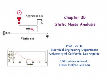
Chapter 3b Static Noise Analysis
Description:
Chapter 3b Static Noise Analysis Aggressor net Cx Victim net Prof. Lei He Electrical Engineering Department University of California, Los Angeles URL: eda.ee.ucla.edu – PowerPoint PPT presentation
Number of Views:190
Avg rating:3.0/5.0
Title: Chapter 3b Static Noise Analysis
1
Chapter 3bStatic Noise Analysis
- Prof. Lei He
- Electrical Engineering Department
- University of California, Los Angeles
- URL eda.ee.ucla.edu
- Email lhe_at_ee.ucla.edu
2
Outline
- Introduction and Motivation
- Noise Models
- RC Model
- J. Cong, Z. Pan and P. V. Srinivas, "Improved
Crosstalk Modeling for Noise Constrained
Interconnect Optimization", ASPDAC 2001 - Worst case noise for RC
- Lauren Hui Chen, Malgorzata Marek-Sadowska
Aggressor alignment for worst-case coupling
noise. ISPD 2000 48-54 - Worst case noise for RLC
- Jun Chen and Lei He, "Worst-Case Crosstalk Noise
for Non-Switching Victims in High-speed Buses",
TCAD, Volume 24, Issue 8, Aug. 2005, Pages 1275
- 1283
3
Introduction
- Coupling Capacitance Dominates
- Signal delay
- Crosstalk noise
- What is Crosstalk noise?
- Capacitive coupling between an aggressor net and
a victim net leads to coupled noise - Aggressor net switches states source of noise
for victim net - Victim net maintains present state affected by
coupled noise from aggressor net
4
Noise Models
- RC model
- J. Cong, Z. Pan and P. V. Srinivas, "Improved
Crosstalk Modeling for Noise Constrained
Interconnect Optimization", ASPDAC 2001 - Worst case noise for RC
- Lauren Hui Chen, Malgorzata Marek-Sadowska
Aggressor alignment for worst-case coupling
noise. ISPD 2000 48-54 - Worst case noise for RLC
- Jun Chen and Lei He, "Worst-Case Crosstalk Noise
for Non-Switching Victims in High-speed Buses",
TCAD, Volume 24, Issue 8, Aug. 2005, Pages 1275
- 1283
5
Aggressor / Victim Network
- Assuming idle victim net
- Ls Interconnect length before coupling
- Lc Interconnect length of coupling
- Le Interconnect length after coupling
- Aggressor has clock slew tr
6
2- p Model
- Victim net is modeled as 2-p -RC circuits
- Rd Victim drive resistance
- Cx is assumed to be in middle of Lc
victim / aggressor coupling capacitance
7
2- p Model Parameters
8
Analytical Solution
9
Analytical Solution part 2
- s-domain output voltage
- Transform function H(s)
10
Analytical Solution part 3
- Aggressor input signal
- Output voltage
11
Simplification of Closed Form Solution
- Closed form solution complicated
- Non-intuitive
- Noise peak amplitude, noise width?
- Dominant-pole approximation method
12
Dominant-Pole Simplification
13
Intuition of Dominant Pole Simplification
- vout rises until tr and decays after
- vmax evaluated at tr
14
Extension to RC Trees
- Similar to previous model with addition of lumped
capacitances - Extended to a victim net in general RC tree
structure
15
Results
- Average errors of 4 comparing to HSPICE in peak
noise and noise width. - Devgan model 589
- Vittal model 9
- 95 of nets have errors less than 10
16
Spice Comparison
- peak noise noise width
17
Effect of Aggressor Location
- As aggressor is moved close to receiver, peak
noise is increased
Ls varies from 0 to 1mm Lc has length of 1mm Le
varies from 1mm to 0
18
Optimization Rules
- Rule 1
- If RsC1 lt ReCL
- Sizing up victim driver will reduce peak noise
- If RsC1 gt ReCL and tr ltlt tv
- Driver sizing will not reduce peak noise
- Rule 2
- Noise-sensitive victims should avoid
near-receiver coupling
19
Optimization Rules part 2
- Rule 3
- Preferred position for shield insertion is near a
noise sensitive receiver - Rule 4
- Wire spacing is an effective way to reduce noise
- Rule 5
- Noise amplitude-width product has lower bound
- And upper bound
20
Noise Models
- Devgans model
- Anirudh Devgan, "Efficient Coupled Noise
Estimation for On-chip Interconnects", ICCAD,
1997. - 2-Pi model
- J. Cong, Z. Pan and P. V. Srinivas, "Improved
Crosstalk Modeling for Noise Constrained
Interconnect Optimization", ASPDAC 2001 - Worst case noise for RC
- Lauren Hui Chen, Malgorzata Marek-Sadowska
Aggressor alignment for worst-case coupling
noise. ISPD 2000 48-54 - Shield Insertion and Net Ordering (SINO)
- L. He and K. M. Lepak, "Simultaneous shield
insertion and net ordering for capacitive and
inductive coupling minimization", ISPD 2000 - Worst case noise for RLC
- Jun Chen and Lei He, "Worst-Case Crosstalk Noise
for Non-Switching Victims in High-speed Buses",
TCAD, Volume 24, Issue 8, Aug. 2005, Pages 1275
- 1283
21
Worst Case Noise Model
- Consider multiple-aggressors situation
- Each aggressor (A1, , A5) has its switching
signal. - Each switching aggressor will result in a
coupling noise on victim at variable arrival
times.
22
Worst Case Noise Model
- To consider Worst Case Noise (WCN)
- Make alignment of aggressor inputs (change
arrival time) - The coupling noise at victim output can occur at
the same time. - Aggressor Alignment Problem Formulation
- Find the relative relationships among arrival
times for all aggressor inputs such that all
individual peak noises are aligned, assuming all
the other conditions are fixed.
23
WCN Superposition
- Consider two aggressors (V1 and V2) case
- N1 when V1 is switching, V2 is quiet
- N2 when V2 is switching, V1 is quiet
Individual noise waveforms
24
WCN Superposition
- To consider WCN, the aggressor alignment is
performed - Change the arrival time of V2
- Two noise signals can occur at the same time
25
WCN Analysis strategies
- Four WCN analysis strategies based on aggressor
alignment - Explicit Aggressor Alignment (AS Aligned
switching) - Noise output is obtained by aligning switching of
all aggressors. The largest amplitude is WCN. - No Aggressor Alignment (SS simultaneous
switching) - Simultaneous switching of all aggressors.
- Implicit Aggressor Alignment (SP Superposition)
- Each noise output is obtained with only one
aggressor switching - Total peak noise is the summation over all
individual peak noise. - Extension of Implicit Aggressor Alignment
- Each noise output is obtained with only one
aggressor switching - back-annotates use output noise to determine
the aggressor input skews, and estimate the
coupling stage again.
26
Noise Models
- Devgans model
- Anirudh Devgan, "Efficient Coupled Noise
Estimation for On-chip Interconnects", ICCAD,
1997. - 2-Pi model
- J. Cong, Z. Pan and P. V. Srinivas, "Improved
Crosstalk Modeling for Noise Constrained
Interconnect Optimization", ASPDAC 2001 - Worst case noise for RC
- Lauren Hui Chen, Malgorzata Marek-Sadowska
Aggressor alignment for worst-case coupling
noise. ISPD 2000 48-54 - Shield Insertion and Net Ordering (SINO)
- L. He and K. M. Lepak, "Simultaneous shield
insertion and net ordering for capacitive and
inductive coupling minimization", ISPD 2000 - Worst case noise for RLC
- Jun Chen and Lei He, "Worst-Case Crosstalk Noise
for Non-Switching Victims in High-speed Buses",
TCAD, Volume 24, Issue 8, Aug. 2005, Pages 1275
- 1283
27
Problem Formulation
- Assume coplanar parallel interconnect structures
(termed a placement),
Vdd
Gnd
s1
s2
s3
s4
- Cx coupling has been considered, but Lx coupling
can not be neglected. - Simultaneous shield insertion and net ordering
(SINO) - Net ordering eliminates Cx noise
- Shield insertion removes Lx noise
28
Characteristics of Lx Coupling
of Shields Noise ( of Vdd)
0 (a) 0.71V (55)
2 (b) 0.38V (29)
5 (c) 0.17V (13)
(18 bit bus structure from He et. al., CICC 1999)
(a)
(b)
(c)
- Lx coupling between non-adjacent nets is
non-trivial - Shielding is effective to reduce Lx coupling
29
Net Sensitivity
- Two nets are considered sensitive if a switching
event on signal s1 happens during a sample time
window for s2
error occurs
Signal levels (V)
aggressor
VIH
victim1
victim2
time
Sampling window
no error occurs
30
SINO/NF Problem Formulation
- Given An initial placement P
- Find A new placement P via simultaneous shield
insertion and net ordering such that - P is capacitive noise free
- Sensitive nets are not adjacent to each other
- P is inductive noise free
- Sensitive nets do not share a block
- P has minimal area
31
SINO/NB Problem Formulation
- Given An initial placement P
- Find A new placement P via simultaneous shield
insertion and net ordering such that - P is capacitive noise free
- All nets in P have inductive noise less than a
given value - P has minimal area
32
Noise Models
- 2-Pi model
- J. Cong, Z. Pan and P. V. Srinivas, "Improved
Crosstalk Modeling for Noise Constrained
Interconnect Optimization", ASPDAC 2001 - Worst case noise for RC
- Lauren Hui Chen, Malgorzata Marek-Sadowska
Aggressor alignment for worst-case coupling
noise. ISPD 2000 48-54 - Shield Insertion and Net Ordering (SINO)
- L. He and K. M. Lepak, "Simultaneous shield
insertion and net ordering for capacitive and
inductive coupling minimization", ISPD 2000 - Worst case noise for RLC
- Jun Chen and Lei He, "Worst-Case Crosstalk Noise
for Non-Switching Victims in High-speed Buses",
TCAD, Volume 24, Issue 8, Aug. 2005, Pages 1275
- 1283
33
Worst Case Noise (WCN) for RLC tree
- Problem Formulation
- Given a non-switching victim and multiple
aggressors in a pre-routed interconnect structure - Object find switching patterns and switching
times for all aggressors such that the noise in
the victim has maximal amplitude. - Recall basic WCN analyses for RC model
- SS Simultaneous switching
- SP Superposition
- AS Aligned switching
How to extend WCN analysis to the RCL model?
34
WCN under the RCL model
- Shielding
- Dedicated shields can reduce crosstalk noise.
- Assume there are shields at both edges of the bus
structure.
Vdd
Gnd
s1
s2
s3
s4
35
WCN under the RCL model
- Switching Pattern
- Waveform can have resonance due to inductance
under RCL model - Resonance leads to multiple noise peaks with
opposite polarities. - WCN may happen when aggressors switch in the same
or different direction.
V quiet victim q q quiet wire a -
aggressor S - shield
36
WCN under the RCL model
- Routing Direction
- Same direction or Opposite direction
- Consider two routing directions
- One is aggressor and the other is victim
- Same direction routing leads to smaller crosstalk
noise - Noise difference results from different current
flow, and different loop inductance.
37
WCN analysis under RLC model
- Extension to Existing Algorithm for RC
- Simultaneous Switching (SS)
- All aggressors switch simultaneously in the same
direction - WCN is the maximum noise on the victim
- Superposition (SP)
- Find maximum noise peak for each aggressor when
only this aggressor switches. - WCN is the summation of amplitudes of all such
peaks.
38
WCN analysis under RLC model
- AS (Aligned Switching)
- Find individual noise with only one aggressor
switching - Switch multiple aggressors to find the maximum
noise - PP alignment
- align the maximum positive peaks of individual
noises - all aggressors switch in the same direction
- NN alignment
- align the maximum negative peaks of individual
noises - all aggressors switch in the same direction
- PN alignment
- align the peaks of maximum amplitude
- Aggressors have switching directions that all the
aligned peaks have the same polarity. - WCN is the maximum noise among the above
simulations.
Recommended
CrystalGraphics Presentations


