
Diapositiva 1 - PowerPoint PPT Presentation
1 / 1
Title:
Diapositiva 1
Description:
... (Oncological Therapy with ... out of the shielding with cooling and ... From thermal calculations the maximum tolerable current density is 35 A/cm2 ... – PowerPoint PPT presentation
Number of Views:24
Avg rating:3.0/5.0
Title: Diapositiva 1
1
A NON LINEAR TRANSPORT LINE FOR THE
OPTIMIZATION OF F18 PRODUCTION BY THE TOP LINAC
INJECTOR C. Ronsivalle, L. Picardi, C.
Cianfarani, G. Messina, G.L. Orlandi
(ENEA-Frascati,Italy), E.Cisbani, S.Frullani,
(Istituto Superiore di Sanità, Roma, Italy)
Abstract The injector of the TOP Linac
(Oncological Therapy with Protons), under
development by ENEA and ISS consists in a 7 MeV,
425 MHz RFQDTL (AccSys Model PL-7). It is
actually in operation at ENEA-Frascati
laboratories for the production of the
positron-emitting radionuclide F18 for PET
analyses by an intense proton beam (8 10 mA, 50
100 ?s, 30 100 Hz). At the exit of the
injector, the beam is guided through a magnetic
channel to a target composed by a thin chamber
(0.35 mm thick and 1 inch diameter) containing
water enriched with O18. Two techniques aimed to
flatten the proton beam distribution and so
optimize the radioisotope production are
compared a spot scanning system and the use of a
non-linear magnet system including octupoles.In
the paper the details of the beam dynamic study
and the first measurements results are presented.
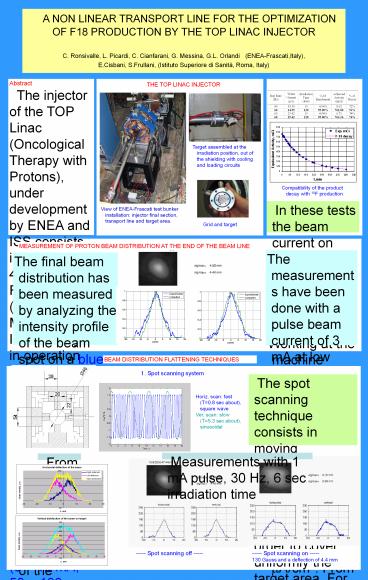
THE TOP LINAC INJECTOR
TESTS OF 18F PRODUCTION
Target assembled at the irradiation position, out
of the shielding with cooling and loading
circuits
Compatibility of the product decay with 18F
production
In these tests the beam current on target was
limited by a non uniform intensity distribution
. Working at the machine maximum ratings an
activity of 1Ci/h could be achieved
View of ENEA-Frascati test bunker installation
injector final section, transport line and target
area.
Grid and target
MEASUREMENT OF PROTON BEAM DISTRIBUTION AT THE
END OF THE BEAM LINE
The measurements have been done with a pulse beam
current of 3 mA at low repetition frequency. The
peak current density extrapolated at the maximum
ratings parameters is between 15 and 18 ?A/cm2.
From thermal calculations the maximum tolerable
current density is 35 ?A/cm2.This value is
compatible with maximum beam currents of 6-7 mA,
that prevents to operate the accelerator at its
maximum pulse current, with consequent reduction
of the F-18 production efficiency. In order to
increase the intensity and so the production
yield a uniform irradiation of the target is
demanded.
The final beam distribution has been measured by
analyzing the intensity profile of the beam spot
on a blue cellophane placed at the end of the
beam transport line. A large number of
measurements has been done for different
quadrupole settings and different irradiation
times of the cellophane. The main problems of
this technique derive from the risk of cellophane
destruction, when the beam spot is very small and
concentrated and from the cellophane saturation
effect for long irradiation time. When the
saturation effects are reduced, shorting the
cellophane exposure times, a triangular shape
appears accordingly with beam dynamics
computations
BEAM DISTRIBUTION FLATTENING TECHNIQUES
1. Spot scanning system
The spot scanning technique consists in moving
magnetically the beam spot in horizontal and
vertical directions in order to cover uniformly
the target area. For our tests we used a 4-poles
scanning magnet. The pole length is 120 mm and
the maximum current is 2 Amp. corresponding to a
magnetic field of 180 gauss. The magnet is placed
at a distance to target of 1100 mm, just after
the second quadrupole, where the beam is large in
horizontal plane and the horizontal deflection
acts only on the central portion of the beam.
- Horiz. scan fast (T0.8 sec about), square wave
- Ver. scan slow (T5.3 sec about), sinusoidal
Measurements with 1 mA pulse, 30 Hz, 6 sec
irradiation time
From simulations
----- Spot scanning off -----
----- Spot scanning on ----- 130 Gauss and a
deflection of 4.4 mm