
Wireless%20Networks:%20Physical%20and%20Link%20Layers - PowerPoint PPT Presentation
Title:
Wireless%20Networks:%20Physical%20and%20Link%20Layers
Description:
Wireless Networks: Physical and Link Layers Wired Typically point-to-point connections Interference effects are not significant Not power constrained Wireless – PowerPoint PPT presentation
Number of Views:232
Avg rating:3.0/5.0
Title: Wireless%20Networks:%20Physical%20and%20Link%20Layers
1
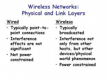
Wireless Networks Physical and Link Layers
- Wired
- Typically point-to-point connections
- Interference effects are not significant
- Not power constrained
- Wireless
- Typically broadcasted
- Interference not only from other hosts, but other
devices/physical world phenomenon - Power constrained
2
Adhoc vs. Wireless LANs
- Adhoc
- Peer-to-peer networking
- Short range (10s of meters)
- One device in multiple networks
- Little supervision/management
- Wireless LANs
- Substitute for wired LANs
- Longer range (100s of meters)
- Typically connected to a wired backplane
- Device typically in only 1 network.
- Needs management
3
Bluetooth A Case Study for Adhoc Networks
- From
- J. Haartsen, The Bluetooth Radio System. IEEE
Personal Communications, Feb 200.
4
(No Transcript)
5
Overview
- Wireless personal area adhoc networking
- Uses 2.45 GHz spectrum (open to public)
- Several miniature networks (called Piconets) can
co-exist. - A host can reside in multiple piconets
- Each piconet channel has 1 master and up to 7
slaves - Unreliable (and shared) medium
- Limited power
6
Multiplexing the bandwidth
- If you do not reserve the slots when someone
should transmit, then there would be a lot of
collisions/contention. - How do you allocate the slots to different hosts?
- In the 2.45 GHz range, we are allowed 2400-2483
MHz, and we need to find out what frequency to
use at each instance of time. - Bluetooth uses 79 frequencies at 1 MHz spacing.
7
The Multiplexing Problem
frequency
(how to divide resource among multiple channels?)
time
8
Frequency-Division Multiplexing
9
Time Division Multiplexing
10
Frequency-Time Division Multiplexing
11
- Bluetooth uses frequency-time multiplexing
(frequency hopping) - You do not want to perform multiplexing
statically (since you do not know what hosts are
present, and who will transmit) - Dynamically determine multiplexing.
- However, if everything is dynamic then we need an
extensive protocol to figure our who transmits
when - Bluetooth uses a frequency hopping pattern
wherein the identity of the master is used to
determine the (sequence of) frequencies that
should be used at each time slot.
12
Frequency Hopping
- Use a well defined hopping pattern sequence for
each piconet.
13
Hop Selection Logic
Master identity chooses sequence Clock chooses
index (phase) in sequence Offset established at
connection time
14
Connection Establishment
- How do units find each other and establish
connections? - No common control unit!
- A unit wakes up to listen (scan) for its id for
around 10 ms. - Wake up hop sequence is 32 hops (cyclic) and
unique for each device. - The burden is on paging unit to ensure the
appropriate unit is woken up.
15
- It knows id of dest, and its wakeup 32 hop
(unique) sequence - It transmits the dest id repeatedly at different
frequencies in the sequence every 1.25 ms
(2625us) - It transmits two dest id codes and listens twice
for a response.
16
Polling Device
- In 10ms (sleep period) 16 frequencies visited
(half sequence) - If polling device does not receive response after
the sleep period, will repeat on the hop
carriers of the remaining 16 in the sequence. - Maximum delay is thus twice the sleeping period
- When dest. receives page, it returns back a msg
with its identity. - Paging unit then sends the dest its identity and
clock, and the two now establish a piconet (pager
becomes master, and dest a slave).
17
Medium Access
- A piconet channel is defined by id and system
clock of Master - All other units are slaves
- When a piconet is established, slaves add offset
to their native clocks to sync with Master - Different channels have different Masters (and
different hopping patterns) - Wired solutions for media access control (e.g.
CSMA) do not suffice.
18
The Hidden Terminal Problem
B
A
C
- A sends to B, C cannot receive A
- C wants to send to B
- If use CSMA/CD
- C senses a free medium, thus C sends to A
- Collision at B, but A cannot detect the collision
- Therefore, A is hidden for C
19
The Exposed Terminal Problem
B
A
C
D
- B sends to A, C wants to send to D
- If use CSMA/CD
- C senses an in-use medium, thus C waits
- But A is outside the radio range of C, therefore
waiting is not necessary - Therefore, C is exposed to B
20
- Master completely controls access control, making
access contention free. - Time slots are alternately used for Master and
Slave transmissions. - The master decides for each slave-gtmaster slot
which slave should get it. - Only the slave addressed in the preceding
master-gtslave slot is allowed to transmit in this
slave-gtmaster slot. - If the master has no information to send, it has
to poll the slave explicitly with a short poll
packet.
21
Master-controlled Media Access
22
Packet Structure(in bits)
23
Acks/Retransmissions
A bit in header is used to indicate whether
previous packet was received correctly (or if a
re-transmission is needed)
Recommended
CrystalGraphics Presentations


