Analysis of Spark Ignition Engine - PowerPoint PPT Presentation
Title:
Analysis of Spark Ignition Engine
Description:
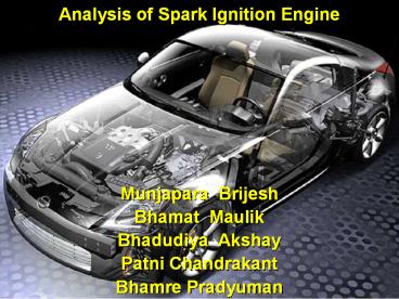
Analysis of Spark Ignition Engine Munjapara Brijesh Bhamat Maulik Bhadudiya Akshay Patni Chandrakant Bhamre Pradyuman Engine Management System Engine Management ... – PowerPoint PPT presentation
Number of Views:172
Avg rating:3.0/5.0
Title: Analysis of Spark Ignition Engine
1
Analysis of Spark Ignition Engine
- Munjapara Brijesh
- Bhamat Maulik
- Bhadudiya Akshay
- Patni Chandrakant
- Bhamre Pradyuman
2
Engine Management System
- Engine Management System Basics
- Advantages of EFI
- Future Trends
3
The Brains of the Car
- Electronic Control Unit or ECU
- Small computer connected directly to engine
- Monitors engine parameters through the use of
sensors - Manages throttle control, ignition, fuel
injection, and power
4
Fuel Mapping
- Through the use of the ECU data and computer
programs the engine can be mapped depending on
speed and load of the engine. - Fuel and timing settings can be adjusted using
these maps to achieve maximum performance from
the engine.
5
Crank Sensor
- Determines speed of engine
- Consists of toothed wheel and an inductive pickup
- Sensor pulses and creates a magnetic field
- Depending on location of wheel, changes magnetic
field strength - From magnetic strength the ECU can tell the exact
crank position and speed
6
Throttle Position Sensor
- Determines the load on the engine
- Two types
- 1) Electronic accelerator pedal
- Senses force applied to pedal and opens throttle
body accordingly - 2) Direct linkage
- Uses a linkage between pedal and throttle
7
Mass Airflow Sensor
- Current setup uses hot wire method
- Heated wire placed in venturi section and air
flows over wire and cools - Measures current required to keep at a constant
temperature - ECU converts voltage drops into mass airflow
8
Lambda Sensor (Oxygen Sensor)
- One of the most important components of the
engine management system - This device is extremely important in fuel
conservation and emissions control - The amount of oxygen present in the exhaust
stream is a direct result of the air/fuel ratio
9
Oxygen Sensor - How it Works
- Sensor consists of two electrodes, one exposed to
air and the other exposed to the exhaust gases - Difference in partial pressures of oxygen
produces a voltage - The ECU reads how much fuel should be injected
based on the voltage - Rich mixtures contain little free oxygen
- Lean mixtures contain considerable free oxygen
10
Temperature Sensor
- Temperatures measured
with a sensor known as a thermistor - A thermistor is a resistor made of a
semiconductor material whose electrical
resistance changes with temperature
11
Pressure Sensor
- Used to monitor intake manifold and ambient
pressures - Measured by semi-conducting silicon diaphragm
that separates two chambers - Pressure change causes diaphragm to flex
- When diaphragm flexes cause resistance of
material to change - ECU monitors voltage change
12
Knock Sensor
- Sensors alert ECU when vibrations are detected in
the cylinder - Knock sensors contain a piezoelectric crystal
- Crystal produces an electric signal when
subjected to physical stress due to engine knock.
- ECU responds by retarding or advancing ignition
time
13
EFI Systems
- Advantages
- Improved fuel distribution
- Engine power increases by average of 10 percent
- Faster acceleration resulting from direct
delivery of fuel to the cylinder - Leaner air/fuel ratios
- better fuel economy
- reduced exhaust emissions
- Decreased engine knock
- Elimination of inlet manifold backfiring and
icing
14
EFI Systems
- Disadvantages
- Cost
- More vulnerable than carburetors
- Require clean fuel and air to operate correctly
- Dirt could cause significant damage to system
15
Future Trends
- Replacement of mechanical and hydraulic linkages
with purely electrical systems - Electronically controlled valve systems
- Faster opening and closing times
- Minimal impact forces
- Optimized fuel consumption and engine power
- Implementation of direct fuel injectors
- Increased fuel efficiency
- Reduced emissions
- Drive-by-wire chassis
- Electronically controlled breaking, steering, and
shifting - Shortened braking distance
- Improved vehicle stability
- Lower maintenance costs
- Potential for remote diagnosis and maintenance
16
Conclusion
- The electronic fuel management system of todays
engines is a revolutionary design that works to
maximize engine performance while reducing
emissions. This new technology allows for
changes in the engine while it is running to
achieve peak performance. These systems will
only continue to improve as technology advances.
17
(No Transcript)

