
Controller design by R.L. - PowerPoint PPT Presentation
Title:
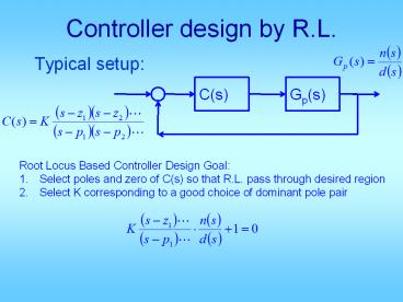
Controller design by R.L.
Description:
Typical setup: C(s) Gp(s) Root Locus Based Controller Design Goal: Select poles and zero of C(s) so that R.L. pass through desired region Select K corresponding to a ... – PowerPoint PPT presentation
Number of Views:180
Avg rating:3.0/5.0
Title: Controller design by R.L.
1
Controller design by R.L.
- Typical setup
C(s)
Gp(s)
- Root Locus Based Controller Design Goal
- Select poles and zero of C(s) so that R.L. pass
through desired region - Select K corresponding to a good choice of
dominant pole pair
2
Types of classical controllers
- Proportional control
- Needed to make a specific point on RL to be
closed-loop system dominant pole - Proportional plus derivative control (PD control)
- Needed to bend R.L. into the desired region
- Lead control
- Similar to PD, but without the high frequency
noise problem max angle contribution limited to
lt 75 deg - Proportional plus Integral Control (PI control)
- Needed to eliminate a non-zero steady state
tracking error - Lag control
- Needed to reduce a non-zero steady state error,
no type increase - PID control
- When both PD and PI are needed, PID PD PI
- Lead-Lag control
- When both lead and lag are needed, lead-lag
lead lag
3
Proportional control design
- Draw R.L. for given plant
- Draw desired region for poles from specs
- Pick a point on R.L. and in desired region
- Use ginput to get point and convert to complex
- Compute K using abs
- and polyval
- Obtain closed-loop TF
- Obtain step response and compute specs
- Decide if modification is needed
4
PD controller design
- Design steps
- From specs, draw desired region for pole.Pick
from region, not on RL - Compute
- Select
- Select
Gpdevalfr(sys_p,pd) phipi - angle(Gpd)
zabs(real(pd))abs(imag(pd)/tan(pi-phi))
Kd1/abs(pdz)/abs(Gpd)
5
Drawbacks of PD
- Not proper deg of num gt deg of den
- High frequency gain ? 8
- High gain for noise
- Saturates circuits
- Cannot be implemented physically
6
- Approximation to PD
- Same usefulness as PD
- Lead Control
- Draw R.L. for G
- From specs draw region for desired c.l. poles
- Select pd from region
- LetPick z somewhere below pd on Re
axisLetSelect
7
- Alternative Lead Control
- Draw R.L. for G
- From specs draw region for desired c.l. poles
- Select pd from region
- Let
- Select
8
Lag control design
- It has destabilizing effect (lag)
- Not used for improving Mp, tr, tp, ts,
- Use it to reduce a non-zero ess
- Use it when R.L. of G(s) go through the desired
region but ess is too large.
9
Design steps
- Draw R.L. for G(s).
- From specs, draw desired pole region
- Select pd on R.L. in region
- Get
- With that K, compute error constant(Kpa, Kva,
Kaa) from KG(s) - From specs, compute Kpd, Kvd, Kad
10
- If Ka gt Kd , doneelse pick
- Re-compute
- Closed-loop simulation tuning as necessary
11
- Example
- Want
- Solution
C(s)
Gp(s)
12
Draw region
13
- Draw R.L.
- Pick pd on R.L. in Region pick pd 0.35
j0.5 - Since there is one in G(s)
14
(No Transcript)
15
(No Transcript)
16
(No Transcript)
17
A better tuning may be to go back and re-pick pd
18
- Lag control can improve ess, but cannot eliminate
ess - Use PI control to eliminate ess
- PI
19
- Only advantage of PI remove ess
- It has destabilizing effect May ? MP , ? ts ,
etc. - Sluggish settling, just like Lag
- Needs trial and error tuning of Kp and KI
20
This way, just use your PDdesign program.
21
- Second design
- Draw R.L. for G(s)
- From specs, draw desired region
- Pick pd on R.L. in region
- i. Chooseii. Choose
- Simulate tune
22
- Example
- Want
- Solution Draw R.L.
C(s)
Gp(s)
23
(No Transcript)
24
- Clearly, R.L. pass through desired region.
- Pick (right on boundary)
- Choose
25
- Step response ess 0
- No MP (no overshoot)
- fast rise to 0.85, then very sluggish to 1
- Tune 1 KP ? to 2.5 KP
26
(No Transcript)
27
- None unique solution
- Design is a creative process guided by science
28
C(s)
G (s)
- Example
- Want
29
- Sol G(s) is type 1Since we want finite ess to
unit acc, we need the compensated system to be
type 2 C(s) needs to have in it
30
(No Transcript)
31
- Draw R.L., it passes through the desired region.
- Pick pd on R.L. in Region
- pick pd 180 j160
- Now choose z to meet Ka
32
- Also
33
- Pick z 0.03
- Do step resp. of closed-loop
- Is it good enough?
34
Design goal
35
- If tr 0.0105 not satisfactorywe need to reduce
tr by 5
36
Label each Root Locus with one TF choice.
J
A
E
D
F
G
H
I
B
C
Recommended
CrystalGraphics Presentations


