
Electrical and Computer Systems Engineering - PowerPoint PPT Presentation
Title:
Electrical and Computer Systems Engineering
Description:
Title: No Slide Title Author: Steve Armstrong Last modified by: Steve Armstrong Created Date: 8/22/2001 2:15:54 AM Document presentation format: Custom – PowerPoint PPT presentation
Number of Views:15
Avg rating:3.0/5.0
Title: Electrical and Computer Systems Engineering
1
IMAGE BASED VISUAL SERVOING
Supervisor Dr. Ming LIU Associate Supervisor
Dr. F. CRUSCA
Seng Guan TAN
INTRODUCTION Vision as a means of non-contact
measurement has been quite popular due in fact
that it is very close to the human visual sense.
The application of vision as a feedback in a
control loop has became a trend because it is a
non-contact measurement method that remains
useful in a non-controlled environment.
Improvement in computing capability allowed a
real-time control to be implemented.
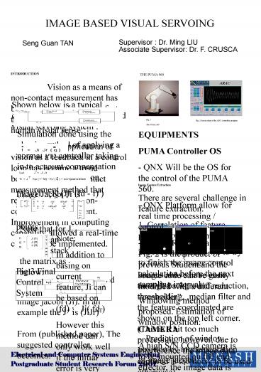
THE PUMA 560
Shown below is a typical control loop for an
image based visual servoing system
Fig. 1 The PUMA 560
Fig. 2 Screen short of the QNX controller program
Simulation done using the classic method of
applying a normal PD controller taking in to
account compensation for gravity and
friction. (V,w)T K (J (fd - f) ) V
(v,w)T J is a control jacobi based on the
pseudo inverse of image jacobi (Ji). In an
example the J is (JiJr)T From (published
paper), The suggested controller becomes
EQUIPMENTS PUMA Controller OS - QNX Will be the
OS for the control of the PUMA 560. - QNX
Platform allow for real time processing /
control. - The ACRA program in Fig. 2 is the
product of previous Student and the source code
can be easily modified with a different
controller. CAMERA A high S/N CCD camera is
to be mounted on the end-effector, the image data
is processed by a independent PC that run in
synch with the PUMA 560 system. Camera Model is
TM - 6E The Video Capture Card used is DT3155.
Image Feature Extraction There are several
challenge in feature extraction. 1. Correlation
of feature points between frames. 2. Processing
time. We to try to finish the image control
calculation before the next sampling
interval Windowing method proposed. Estimation of
window position - Prediction of window position
by implementation of image jacobi f f(old)
Ts x Ji (v,w)T (v,w)T from the
controller. - A general fixed estimation based
on previous feature coordinate. Assuming a slow
feature velocity.
Image Jacobi Ji is actually based on the current
feature points
.
Ji
f
Note that for Ji (f1) we can actually stack the
matrix as below
Note In addition to basing on current feature,
Ji can be based on (fd) Ji( fd ) However this
method can only work well if the initial error is
very small. It is used to avoid reaching a local
minima in the J matrix
a b c
Fig. 3 (a),(b) location shown on top left
corner (c) with cross section of line showing
current feature point.
Fig 3 Final Control System
Images above have gone through background
reduction, thresholding, ,median filter and the
feature coordinated are shown on the top left
corner. (This is a bit too much processing,
however, due to interference the image data
captured is too noisy to be used
otherwise) Processing time (without display) was
around 0.4 s in a Pentium3 888Hz (768 x 576
pixel) By implementing the windowing method time
is greatly reduced 0.032s (camera acquisition
30fps rate ) The new timing include an additional
edge detection process. Still the process should
be improved, since the control algorithm will be
taking its own processing time. (0.1s total)
sampling time is currently being considered.
Electrical and Computer Systems
Engineering Postgraduate Student Research Forum
2001
Recommended
CrystalGraphics Presentations


