
DMU: Kinematics Workbench - PowerPoint PPT Presentation
Title:
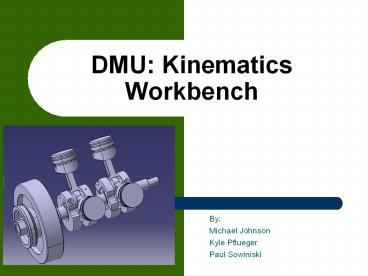
DMU: Kinematics Workbench
Description:
DMU: Kinematics Workbench By: Michael Johnson Kyle Pflueger Paul Sowiniski Overview Mechanisms Joints Commands Simulations Animate Speeds and Accelerations Data ... – PowerPoint PPT presentation
Number of Views:143
Avg rating:3.0/5.0
Title: DMU: Kinematics Workbench
1
DMU Kinematics Workbench
- By
- Michael Johnson
- Kyle Pflueger
- Paul Sowiniski
2
Overview
- Mechanisms
- Joints
- Commands
- Simulations
- Animate
- Speeds and Accelerations
- Data Analysis
3
Basic Assembly
- The following is a simple example of a piston
engine - In the assembly design workbench
- Add basic concentric, planer and surface contact
mates
4
Converting Constraints
- While still looking the assembly open the DMU
kinematics workbench - Click the assembly constraint conversion button
- Click new Mechanism and name it
5
Joints
- Once the mechanism has been created, go through
the joints in the tree and double click on the - joints that need to be defined to limit the DOFs
(degrees of freedom). - One you have double clicked on the particular
joints, it will then create a command. - If you are defining a revolute joint, select
angle driven in the menu and set the boundaries.
6
Commands
- Now you can select the Simulation button and
slide the Commands previously created through
their range of movement. - By simply sliding the bars you can determine
which Command will drive the simulation. - Also, remember which Command it is, so later it
will be easy to define a time based formula.
7
Simulation
- Now you can select the Simulation button and
slide the Commands previously created through
their range of movement. - By simply sliding the bars you can determine
which Command will drive the simulation. - Also, remember which Command it is, so later it
will be easy to define a time based formula. - Here is the Mechanism Analysis menu. It will tell
you the status of the mechanism and whether
enough Commands have been added to fully define
it.
8
Animating
- Select the Command which you want to be the focus
of the Simulation by either clicking or dragging
the slide that corresponds with the Command - Then in the window on the right select insert
- The button below the skip to start button can
be toggled to three different settings - The current setting plays through once and stops
at the end - The drop down box on the right allows you to set
how quickly the animation plays
9
Creating a Point
- To output the data for a point we must first have
a point to track. To create one just double click
on a component and define a point.
10
Speeds and Accelerations
- Click on the Speed and Acceleration button to
access this menu. - Select a stationary part as a reference
product, in this case the engine block. - Then select the point you wish to track, the
point that was just created. - Now click Simulation with Laws, the window on
the right will appear.
11
CATIA Acquiring Data
- Placing and activating sensors
- Having selected the appropriate mechanism to
simulate, click activate sensor in the kinematics
simulation player - It is important that once the sensors activated
that the appropriate point of analysis is
selected - Having activated the sensors and selected the
point to analyze the type of data collected must
be selected - Makes sure to toggle the Sensors to Yes for in
order to activate them
12
Sensors
- Another key step prior to simulation is defining
the number of samples desired over the course of
the simulation - This is done in the number of samples drop down
in the kinematic player - One can either used the predefined numbers in the
drop down or manually input the value
13
Analysis in CATIA
- Each line represents a sensor
- Here we show the acceleration, speed and
displacements - Data can be exported to excel
14
Processing
- Once you check Activate sensors the window on
the left will appear now you can select which
pieces of data you want to output data for - Graphics will show you a graph within CATIA,
File will allow you to export the data to Excel
15
Conclusion
- Now you should be able do run kinematic
dialogistic on an assembly in CATIA.
Recommended
CrystalGraphics Presentations


