
Models and modelling languages - PowerPoint PPT Presentation
Title:
Models and modelling languages
Description:
Title: UML Klassdiagram - Grunder Author: Perjons, Thelemyr Last modified by: db2admin Created Date: 5/22/2004 6:23:16 PM Document presentation format – PowerPoint PPT presentation
Number of Views:43
Avg rating:3.0/5.0
Title: Models and modelling languages
1
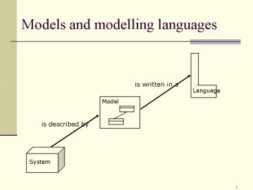
Models and modelling languages
is written in a
Language
is described by
System
2
The reality three levels
People carrying out manual activities
Peolpe interacting with computers
Computers carrying out automatic activities
3
The reality and models three levels
Business processes (in Activity Diagram)
Communication between people (in Sequence
Diagram)
Business concepts (in Class Diagram)
Use Case
Sequence Diagram
Activity Diagram
Information Model (in Class Diagram)
The reality
Graphical models/diagrams
4
What is a graphical model?
- A graphical model is a simplified and visualized
description of a phenomenon (most often a
system).
- A graphical model is made for a certain purpose
for example an aid for analysing a business or
as the basis for building an information system.
5
Why graphical models?
Graphical models reduce the complexity by hiding
less important objects of a system and visualise
the important ones
- Graphical models will give overview and
structure which is important when analysing and
understanding complex systems.
- Graphical models will facilitate communication
between people. Therefore, graphical models can
be an efficient tool for making people agree on
problems and solutions.
6
Graphical models in system development
- - Analysing tools facilitates analysis of a
business. - - Design descriptions drawings over the system
to be developed or changed. - Validating instrument i.e. to validate the
system towards customers and users with the help
of graphical models, so that the system gets
correct qualities before its done developed. - Contact between customers and developers.
7
Two different kind of models
Structural Models / Structure Diagrams
- specifies static aspects of a system , i.e
static relations / relations between terms.
Behavioral Models / Behavioral Diagrams
- Specifies dynamic (behavioral) aspects of the
system, i.e. specifies the - manipulation / the change of the static
relations and in what order it occurs.
8
Models structural and behavioral
- Structural Models/ Structure Diagrams
- Behavioral Models/ Behavioral Diagrams
models/diagrams
9
Models are written in a language
Terms/concepts in a UML Class Diagram language
class attribute method association
Terms/concepts in a UML Activity
Diagram language action flowbranch join
Language
Language
is written in a
is written in a
Behavioral Diagram
Structural Diagram
Terms/concepts in a Structural Diagram customero
rderorder number
Terms/concepts in a behavioral Diagram receive
ordercheck order deliver order
is described by
is described by
System
Kleppe et al, 2003
10
The notation of the language/syntax and semantics
Graphical modelling language contains Notation/sy
ntax -- states which symbols there are in the
language and how they look like, how they can be
combined, and how they are related to the
concepts of the language, for example that an
arrow represents the concept flow. Semantics
defines the central concepts of the language. The
concepts are usually defined in form of a
Conceptual Model called Meta Model.
Language
is written in a
Diagram
11
A UML-diagram is based on a language
UMLs Structure Diagrams and Behavioral Diagrams
are written in the same language
Language
is written in a
is written in a
Behavioral Diagram
Structural Diagram
Concepts in a Structural Diagram customer,
order, order number
Concepts in a Behavioral Diagram order is
received, order is controlled
System
is described by
is described by
Kleppe et al, 2003
12
Models, languages and Meta Models
Concepts in the UML Meta Model class,
associationaction, flow
Concepts in the UML language class,
associationaction, flow
Concepts in diagrams customer, order, order
number
is written in a
Is defined by
is described by
System
Kleppe et al, 2003
13
Graphical modelling languages
Examples of graphical modelling languages UML,
E(A)R diagram, Petri nets, Event-Process Chain
(EPC), IDEF0, IDEF3, Data Flow Diagram,
Role-activity diagram (RAD), database diagram.
Some graphical modelling languages are more
expressive than others. One of the reasons for
that is that certain graphical modelling
languages contains more modelling elements
(symbols). They can then represent more concepts,
i.e. more aspects of the reality (the system).
One disadvantage is that such a language contains
more modelling terms for the user to learn.
14
Modelling concepts a comparison
Database Diagram
E(A)R-Diagram
Class Diagram
Table
Entity
Class
Foreign key
Relation
Association
Column
Attribute
Attribute
Multiplicity
Multiplicity
Multiplicity
Row or post
Instance
Object
Yet note that the terms not always at all, stands
for the same concept!
15
The relation concept and term
Concept
Term
Computer
16
Concepts
- Concepts are a mental representation of one or
more phenomena in the reality, like for example
Concept
- existing objects (expressed with substantives)
- aktions and events (expressed with verbs or
substantivized verbs, for example registration) - relations and positions (expressed with
substantives, adverbs or conjunctions) - quality (expressed with adjectives)
Term
Computer
- A concept can only represent one phenomenon
(Nisse), or via abstraction cover all phenomena
that have certain common characteristics
(Student).
Hedin et al, 2000
17
Term
Concept
A term is a more or less arbitrary symbol
for a concept.
Term
Computer
A term can consist of articulated sound, a
word in form of letters, a group of words, or a
graphical symbol.
Term and word can be seen as synonyms, but
some authors means that a word is becomming a
term when it is defined as a component in a
terminological system. Terms within a certain
area constitutes a terminological system
(terminology).
Hedin et al, 2000
18
The relation concept and term
Concept
- To use a concept it has to be a term for it.
Term
- All terms refers to concepts.
Computer
- The connection between concept and term should be
as unambiguous as possible, otherwise
interpretation problems arises, like - - synonymy
- - polysemy
- - homonymy
Hedin et al, 2000
19
The relation concept and term
Concepts
Terms
x
Synonymy
Different terms refer to the same concept (UML
and Unified Modeling Language refer to the same
thing)
A
y
z
Polysemy
A
The same term refers to different concepts. Often
due to that new meanings for old terms are
stipulated. (democracy)
x
B
x
Homonymy
A
Terms that sounds or are spelled the same way
with different meanings. Light
B
x
x
C
Hedin et al, 2000
20
Delphic versus cryptical languages
Social-science researchers are often using a
vague language (delphic language), which causes
a number of polysemy.
Natural scientists use a cryptical language
which all the time fills up with new terms and is
therefore difficult to understand for
non-specialists.
Hedin et al, 2000
21
Ogdens triangle
Charles Ogden (1889-1957) interested himself in
the connection between - the term (the
linguistic expression) - the concept (the mental
idea, the intension) - the referent (the
phenomenon in the reality, the extension)
Concept
Referent
Term
Ogdens triangle
Computer
22
Ogdens triangle
Ogdens triangle shows that a person has a mental
idea (concept) about a phenomenon in the reality
(referent) and to communicate with others he/she
uses a symbol (term). Also note that to
communicate a phenomenon in the reality
(referent) we can either point at it or try to
convey our idea about the referent via the
language for example with the help of a
conceptual definition.
Concept
Referent
Term
Ogdens triangle
Computer
23
Problem to interpret the reality
The same phenomenon in the reality (referent) can
cause different mental ideas (concepts) because
of different understandings. A classical example
is the planet Venus, which can be interpreted as
two different concepts Morning star and
Evening star.
Concept
Referent
Ogdens triangle
Server
Monitor
Term
24
Ogdens triangle problems analysis
Concept
- Problem concept - referent
- The reality is interpreted different because of
different understandings
- Problem concept - term
- Synonymy
- Homonymy
- Polysemy
Term
Referent
Computer Server Monitor
25
Ogdens triangle what does this mean ....
Concept
- Conceptual definition
- Conceptual Model
- Terminology
Term
Referent
Computer Server Monitor
26
Conceptual modelling
- A Conceptual Model starts from a mental idea och
tries to render a part of the reality in form of
a graphical idea.
- Conceptual modelling is an instrument
- - to analyse and define the concepts no
matter what we call them (what terms we are
using), - - to state a terminology, i.e. which terms
will be used.
0..
Student
Course
0..
Hedin et al, 2000
27
Ogdens triangle
Concept
x
married to
married to
y
Term
Nisse
Anna
x
Referent
Nisse
married to
y
Anna
28
Ogdens triangle
Concept
Anna
married to
married to
Nisse
Term
Nisse
Anna
x
Referent
Nisse
married to
y
Anna
Recommended
CrystalGraphics Presentations


