
Properties of a stationary wave (2) - PowerPoint PPT Presentation
1 / 66
Title:
Properties of a stationary wave (2)
Description:
Title: Diffraction of Light Author: Tang Wai In Last modified by: lcf Created Date: 2/4/2001 10:38:55 PM Document presentation format: – PowerPoint PPT presentation
Number of Views:100
Avg rating:3.0/5.0
Title: Properties of a stationary wave (2)
1
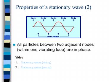
Properties of a stationary wave (2)
- All particles between two adjacent nodes (within
one vibrating loop) are in phase.
- Video
- Stationary waves (string)
- Stationary waves (sound)
2
4 Interference
- When two waves meet, they interfere.
- Superposition occurs to give constructive and
destructive interferences. - To produce a permanent interference pattern, the
sources must be coherent. - The waves from coherent sources have
- (1) the same frequency,
- (2) the same wavelength,
- (3) constant phase difference.
3
- If their phase difference is not constant, at a
certain point, there may be reinforcement at one
instant and cancellation at the next. If these
variations follow one another rapidly, the
interference pattern will change quickly. - The wave causing interference should have roughly
the same amplitude. This is to ensure the wave
cancel each other to produce a minima (zero
amplitude).
4
Constructive interference The waves arrive at
a point in phase
5
Destructive interference The waves arrive at a
point exactly out of phase.
6
Factors affecting the interference pattern
- (1) Source separation
- When source separation increases, the separation
between antinodal (or nodal) lines decreases.
Increase the separation of two sources
7
- (2) Wavelength
- When wavelength decreases, the separation
between antinodal (or nodal) lines decreases.
Decrease the wavelength
8
Youngs experiment
http//www.fed.cuhk.edu.hk/sci_lab/download/projec
t/interference/interference.html
9
Youngs double-slit experiment
- It is very important to use a single light source
and a double slit, rather than two light sources.
It is because the two sets of light waves passing
through the double-slit are coherent. - Since the wavelengths of light waves are very
small, the separation between the slits must be
very small. - The screen should be placed at an appreciable
distance from the slits so that the separation of
fringes is observable.
10
Interference pattern of light
- Explanation
- Diffraction of light occurs at each slit. Since
the two diffracted waves overlap, interference
occurs. - Bright fringes are where constructive
interference occurs while dark fringes are where
destructive interference occurs.
11
Path difference for Youngs double-slit experiment
Since a ltlt D, PX and PY are almost parallel ? q
a and ? PQY 90o By geometry q a ? q q
Path difference PY PX QY a sin q.
12
Path difference for Youngs double-slit experiment
Path difference a sin q.
Constructive interference If the nth bright
fringe is at P, a sin qn nl ?
Destructive interference If the mth bright
fringe is at P, a sin qm (m ½) l ?
13
Fringe position
Path difference a sin q.
nth bright fringe Let yn be the distance between
the nth bright fringe and the central bright
fringe.
yn D tan qn D sin qn
14
Fringe position
15
2. The fringe spacing for red light is
greater than for blue light.
? lred gt lblue 3. The interference is
incomplete because for all fringes except the
central bright one, the amplitudes of the two
wave-trains are not exactly equal.
16
Appearance of Youngs interference Fringes
http//micro.magnet.fsu.edu/primer/java/doubleslit
/index.html
- If white light is used the central fringe is
white and the fringes on either side are coloured.
17
Interference Fringe Pattern
18
Measuring wavelength of light
l can be measured by using the formula
http//www.matter.org.uk/schools/Content/Interfere
nce/doubleslits_1.html
19
Interference by Thin Films
- Thin film interference patterns seen in
Thin film of soapy water
Seashell
A thin layer of oil on the Water of a street
puddle
20
(No Transcript)
21
Parallel-sided Thin Film (1)
- Consider a film of soap with uniform thickness in
air
When a beam of light is incident on to the
surface of the film, part of incident light is
reflected on the top surface and part of that
transmitted is reflected on the lower surface.
air
If the film is not too thick, the two reflected
beams are close together to produce an
interference effect.
Soap film
http//webphysics.davidson.edu/physlet_resources/b
u_semester2/c26_thinfilm.html
22
Phase change of p
- Interference occurs for rays 1 and 2
Suppose the thickness of the film is d and its
refractive index is n. Let l be the wavelength of
light in air. Consider almost normal incidence
(angle of incidence 0o) Interference due to
reflected rays (Optical) Path difference for
rays 1 and 2 2nd
23
Phase change of p
If light travelling in a less dense medium is
reflected by a dense medium, the reflected wave
is phase-shifted by p. No phase change will be
experienced by transmitted rays. (Optical) Path
difference for rays 1 and 2 2nd Conditions for
constructive interference and destructive
interference
Bright fringes 2nd (m ½)l where m 0, 1,
2, 3.. (a phase change of p occurs at
A) Dark fringes 2nd ml where m 0, 1, 2,
3..
24
- Interference due to transmitted rays (ray 3 and
ray 4)
Bright fringes 2nd ml where m 0, 1, 2,
3.. (no phase change of p occurs at B) Dark
fringes 2nd (m ½)l where m 0, 1, 2, 3..
25
Blooming of Lenses (1)
- The process of coating a film on the lens is
called blooming. - A very thin coating on the lens surface can
reduce reflections of light considerably. - This makes use of destructive interference of
light to reduce the reflection.
http//users.erols.com/renau/thinfilm.html
26
- Path difference of the rays 2nd
- For destructive interference between rays 1 and 2
- 2nd l/2 (both rays undergo a phase change of
p) - d l/(4n)
Thickness of coating Put l 5.5 x 10⁻⁷ m, n
1.38 (refractive index of coating) d 5.5 x 10⁻⁷
/ (4 x 1.38) 9.97 x 10⁻⁸ m
27
- Note
- 1 The thickness of the film (coating) should be
of ¼ wavelength of light in the film. - 2. With suitable blooming, the reflectance can be
reduced from 4 to less than 1. - 3 The interference is complete for one wavelength
only. An average value of l (i.e. green
yellow) is chosen. For red and blue light, the
reflection is weakened but not eliminated and
bloomed lens appears purple.
28
- While destructive interference occurs between
reflected rays, constructive interference occurs
between transmitted rays. - If there is constructive interference on one side
of the film, there will be destructive
interference on the other side (energy
conservation).
29
Brilliant colours of oil film on water
Investigating oil film on water Brilliant
colours of oil film
30
- Interference occurs between two wave-trains one
reflected from the surface of the oil and the
other from the oil-water interface. - When the path difference gives constructive
interference for light of one wavelength, the
corresponding colour is seen in the film.
31
- The path difference varies with the thickness of
the film and the angle of viewing, both of which
affects the colour produced. - If the film is not thin, for a particular angle
of viewing, constructive interference between
reflected rays occurs for more than one colour.
Therefore, many colours are present in the
reflected light. This gives the appearance of
white light and no specific colour is seen.
32
Soap film
- A soap film mounted on a ring is held vertically.
At first the film appears uniformly bright. As
the soap drains to the bottom, a series of
interference fringes are seen.
33
Soap film
- For normal incidence, bright fringes are observed
if - 2nd (m ½) l ,
- where n is the refractive index of soap, l is
the wavelength of light in air, and m 1, 2, 3,
- Minimum thickness of the film for bright fringe
- dmin l /(4n)
- Hence, when the upper part of the film becomes
extremely thin lt l /(4n), constructive
interference does not take place and a black area
or black fringe is observed.
34
- As time goes by, the film drains downwards
further and does not break, the fringe pattern
changes - Dark area at the top increases and moves
downwards. - The number of fringes increases.
- Fringes are more closely spaced towards the
bottom.
35
- The figure above shows an air wedge formed by a
thin film and a glass block. They are separated
by a thin piece of paper so that the wedge angle
q is very small. - In the arrangement, monochromatic light from a
source is partially reflected vertically
downwards by a glass plate G. - When a microscope is focused on the wedge, bright
and dark equally-spaced fringes are seen. - This is because the reflected rays interfere with
each other to form an interference pattern.
36
Thin Film of Air
- Light rays reflected from the upper and lower
surfaces of a thin wedge of air interfere to
produce bright and dark fringes. - The fringes are equally spaced and parallel to
the thin end of the wedge.
http//www.gg.caltech.edu/zhukov/applets/film/app
let.html
37
(No Transcript)
38
Thin Film of Air
- Consider almost normal incidence.
- Path difference of two rays 2d
- For dark fringes, 2d n?.
- For bright fringes, 2d (n½)?.
d
?
39
Thin Film of Air, Wedged-shaped (2)
Fringe separation For two adjacent dark fringes,
Dd ½ml (m 1)l ½l
40
- Note
- 1. If the path difference gt coherent length, no
fringe is formed. - 2 In order to have a clear fringe pattern, the
fringe separation should be increased. This can
be done by making the air wedge as thin as
possible. - 3 At the practical level, every film absorbs some
of the light going through it. Thick films absorb
proportionately more than thin ones, thereby
reducing the dark and light bands in an
interference pattern.
41
- Applications of air wedge
- Measuring diameter of a metal wire
Suppose the distance between the 1st fringe and
the 91st fringe observed is 16.2 mm and the
wavelength of light emitted from the light source
is 690 nm. Fringe separation Dx 16.2 mm / 90
0.18 mm Angle of the wedge
If the length of the air wedge is 5 cm, the
diameter of the metal wire d 5 cm x 1.91 x 10-3
9.58 x 10⁻³ cm 9.58 x 10⁻⁵ m
42
- 2. Testing the flatness of surface
- In making of optical flats, the plate under
test is made to form an air wedge with a standard
plane glass surface. - Any uneven parts of the surface will show up as
irregularities in what should be a parallel,
equally-spaced, straight set of fringes.
43
(No Transcript)
44
(No Transcript)
45
Find the thickness of the air wedge at
P. Wavelength of white light l 5.5 x 10⁻⁷ m
x P
At P, destructive interference occurs between the
reflected rays. Path difference l 2t l t l
/ 2 2.75 x 10⁻⁷ m
46
Find the thickness of the air wedge at
Q. Wavelength of white light l 5.5 x 10⁻⁷ m
x Q
At Q, constructive interference occurs between
the reflected rays. Path difference 1.5 l 2t
1.5l t 1.5l / 2 4.125 x 10⁻⁷ m
47
Thickness of air wedge around the ring is equal.
48
Flatness of Surfaces
- Observed fringes for a wedged-shaped air film
between two glass plates that are not flat.
- Each dark fringe corresponds to a region of equal
thickness in the film. - Between two adjacent fringes the change in
thickness is ?/2µ. - where µ is the refractive index of the film.
49
Newtons Rings (AL only)
- When a curved glass surface is placed in contact
with a flat glass surface, a series of concentric
rings is seen when illuminated from above by
monochromatic light. These are called Newtons
rings.
50
Diffraction pattern through an obstacle
51
Diffraction Patterns
52
Interference by multiple slits
- The following shows interference fringes by a
single slit, double-slit and 3 slits, 7 slits and
15 slits with the use of monochromatic light and
white light.
Computer simulations
53
- The locations of the principle maximum are the
same for any number of slits. - As the number of slits increases,
- the width of maximum becomes narrower (sharper),
- intensity of maximum increases (brighter), and
- the sub peak between any two maxima falls.
54
Diffraction grating
- A large number of equally spaced parallel slits
is called a diffraction grating.
- A diffraction grating is made by making many
parallel scratches on the surface of a flat piece
of transparent material. The scratches are opaque
but the areas between the scratches can transmit
light. Thus, a diffraction grating becomes a
multitude of parallel slit sources when light
falls upon it.
55
Diffraction grating VS double slit
- For measuring wavelength of light accurately, a
diffraction grating is used - Diffraction grating can achieve a sharper and
brighter fringe pattern. - Angular separation of fringes can be made larger
by using a diffraction grating as slit separation
can be made many times smaller.
56
- Types of grating
- 1. Transmission grating ? Light passes the spaces
between lines. - 2. Reflection grating ? Light reflects on the
unruled parts. - Fine and coarse grating
- A fine grating (e.g. 600 lines / mm.)
- A coarse grating (e.g. 100 lines /mm)
57
Typical pattern using white light
- A typical pattern consists of
- 1. a central bright band, called the zero
order image, is white - 2. on either side of the central band, there
are brilliant bands of colours, called first
and second order spectra. - Note Dispersion increases with order.
58
Theory of diffraction grating
Monochromatic light
1st order maximum (m 1) Zero th order
maximum (m 0) 1st order maximum
(m -1)
A
B
Diffraction grating
- Consider wavelets coming from points A and B on
two successive slits and traveling at an angle q
to the direction of the incident beam. - Path difference between the ray X and Y d sin
q. - For constructive interference (mth order maximum)
- d sin q ml
59
- Example
- Find the wavelength of light if the angle turned
for 1st order maximum is 20o when a diffraction
grating of 500 line / mm is used. - Solution
- For 1st order maximum,
- d sin q l where d 1mm / 500 2
x 10-6 m - The wavelength of light l 2 x 10⁻⁶ sin 20o
- 6.84 x 10⁻⁷ m
60
- For constructive interference (mth order maximum)
- d sin q ml
- Find all the values of q for all red fringes.
- (l 7 x 10⁻⁷ m, diffraction grating 200
lines per mm) - Solution
61
Maximum number of colour fringes
- The number of orders of maximum is limited by the
grating spacing d and the wavelength l. - For a diffraction grating of 5000 lines / cm,
slit spacing d 1 cm / 5000 2 x 10⁻⁶ m - Maximum for red light is achieved when
We can at most observe the 2nd order red fringe.
62
- Similarly, for the highest order of violet fringe
observed, - We can should be able to observe the 5th
order violet fringe. - The highest order maximum is the greatest integer
.
63
Overlapping of colour bands
64
Example 3
- Show that 2nd order orange fringe will overlap
with 3rd order violet fringe. - It is given that the wavelengths for orange light
and violet light are 6 x 10⁻⁷ m and 4 x 10⁻⁷ m
respectively.
Solution For 2nd order orange fringe,
For 3rd order violet fringe,
? qorange2 qviolet3 ? 2nd order orange fringe
overlaps with 3rd order violet fringe.
65
- For 3nd order violet fringe,
- Hence, 2nd spectrum overlaps with 3rd spectrum.
- For 2nd order red fringe,
66
Application of diffraction grating
- A diffraction grating can be used to determine
the wavelength of waves emitted by a source. - A diffraction grating is placed in front of a
methane air flame (left) and methane oxygen flame
(right).
By comparing the spectra produced, we can decide
which flame is hotter. Why?
Recommended
CrystalGraphics Presentations


