
Flow Visualization Using Fur Simulation - PowerPoint PPT Presentation
Title:
Flow Visualization Using Fur Simulation
Description:
Title: Flow Visualization Using Fur Simulation Subject: Computer Graphics Author: Alex D'Angelo Keywords: flow visualization, scientific visualization, fur, shell ... – PowerPoint PPT presentation
Number of Views:112
Avg rating:3.0/5.0
Title: Flow Visualization Using Fur Simulation
1
Flow Visualization Using Fur Simulation Alex
DAngelo and Alex Pang (advisor)Department of
Computer Science, University of California, Santa
Cruz
Abstract
Texture Generation
Fur and hair are not typically uniform in color
but instead are many slightly different shades.
We wanted to simulate this using a single texture
map. I chose to use a 512x512 pixel texture map
since it allows for enough detail while being
supported by most hardware. The texture map
was generated in Photoshop by applying in order
to a white background add noise, motion blur,
crystallize, hue and saturation, auto contrast,
and finally auto levels. The resulting texture
is filled with chunky colors of slightly
different hues, which is what was wanted. When it
is alpha-blended on the shells, the appearance of
streaks of slightly different colors in the hair
is achieved. In addition, the color of the fur
can be changed by simply changing the hue of the
texture. One drawback to using a single texture
is that the fur must be generally straight. To
simulate hair that is curly or wavy, a small
patch of 3D hair can be procedurally generated
and then sliced into several textures, which are
then used on successive shells. The power of this
approach is that we can sample any kind of 3D
volume and use it as a 3D texture. Fur is only
one of the metaphors for this technique. Other
metaphors include grass, streamers, trees,
buildings, puffy clouds or other arbitrary
models.
Flow visualization is frequently used in the
scientific and engineering communities to
visualize events such as weather data, shock
waves, and the turbulent vortices in the exhaust
of a rocket. There are many techniques available,
including streamlines, streaklines, and LIC. Hair
and fur simulation can also be used to view the
effects of flow data on a surface by analyzing
the movement of patches of hair and the hair as a
whole. Although rendering each hair as a
geometric object is the most physically accurate
representation, it is computationally intensive.
An alternative technique is to take a 3D volume
of hair and slice it horizontally into layers,
which are used to generate textures. By applying
the textures to a 3D model on successive
shells, the appearance of fur is created. We
show simulated fur on arbitrary objects in order
to show how the fur moves when simple forces,
such as wind, are applied.
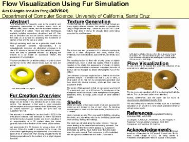
Left to right, top to bottom Side view of a
surface as the number of shells are increased.
The shells are extruded along the vertex normals,
shown in red. When viewed from the top they blend
together to produce a patch of fur, as seen in
the fourth image.
Flow Visualization
To see what the fur looked like under the
influence of an external force, wind was
applied. The fur moves as expected, with
the fur aligning itself with the airflow. This
can be seen better when animated. Movies,
screenshots, and the paper can be found at
www.cse.ucsc.edu/research/avis/fur.html We are
testing more complex models such as a synthetic
simulation of an aircraft in a wind tunnel and
believe that we will get similar results.
Torus before and after fur is applied
Fur Creation Overview
Fur is modeled using a volume texture containing
a patch of hair. The advantage is that a fully
solid approximation of the image can be sliced in
any direction to get a solid cross-section. The
drawback is that even a small volumetric texture
requires much more memory than 2D textures, plus
on current hardware 3D textures are slow and not
supported very well. Our approach to modeling fur
(as described in 12) is the shell-and-fin
method. This technique is where successive
concentric texture-mapped models are drawn,
resulting in an approximation of a 3D surface
when the viewer generally looks in the direction
of the normal of the surface. We approximate the
3D textures by using a stack of 2D textures. When
the model is projected to the screen, the shells
blend together giving the appearance of a
continuous patch of fur. It works best when
looking straight into the fur (looking
perpendicular to the surface) and at slight
degrees from that.
Shells
Shells are copies of the base model which are
successively scaled up and layered on top of each
other. By blending several layers of shells and
the base model, the illusion of fur is
created. Vertex normals are key! They are used
for lighting, extruding the shells, and
interacting with the fur (including global and
local combing, fluffing, and matting). The shells
are extruded along the vertex normals. They are
drawn starting at the base model and moving
outwards. The shell closest to the skin is drawn
opaque but successive shells fade out as they
move further away from the model along the vertex
normal. Each successive shell is modulated with
the light and blended with the shells underneath
it.
References
1 Lengyel, J. Real-time fur. Eurographics
Rendering Workshop 2000, pp.243-256 2 Lengyel,
J., Praun, E., Finkelstein, A., and Hugues, H.
Real-time Fur over Arbitrary Surfaces. ACM 2001
Symposium on Interactive 3D Graphics
Acknowledgements
I would like to thank nVidia and ATI for their
generous donations of hardware for this project.
I would also like to thank Cowell college at UCSC
for being named a Presidents Undergraduate Fellow
in support of this project.