
FOCUSING DIRC PROTOTYPE - PowerPoint PPT Presentation
Title:
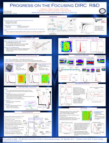
FOCUSING DIRC PROTOTYPE
Description:
Progress on the Focusing DIRC R&D Calorimeter: track energy distribution e-I. Bedajanek, J. Benitez, J. Coleman, D.W.G.S. Leith, G. Mazaheri, B.N. Ratcliff, J ... – PowerPoint PPT presentation
Number of Views:27
Avg rating:3.0/5.0
Title: FOCUSING DIRC PROTOTYPE
1
Introduction
- BABAR-DIRC has been a very successful particle
identification (PID) system - crucial to success of SLAC B-Factory
- very reliable, robust, easy to operate
- p/K separation 2.7s up to 4.2GeV/c
- Potential DIRC for PID at future experiments?
- Super B-Factory Hadron spectroscopy (GlueX
at JLab) - Linear Collider Nuclear physics (PANDA at
GSI) - In many future applications, need to further
improve momentum coverage and make DIRC more
background resistant - ? Improve single photon timing and angular
resolution, decrease size of Cherenkov ring
expansion region - ? SLAC RD for a fast Focusing DIRC, measure
performance of prototype in test beam at SLAC
BEAM DETECTORS Event Selection Start Time
NEXT GENERATION DIRC
Cherenkov Counter Scintillator corrected
event time
Hodoscope single track hit map
- Improve single photon Cherenkov angle resolution
- use smaller photon detector pixels
- correct chromatic production term via precise
timing - use focusing optics to decrease bar size term
- Decrease size of expansion region
- smaller expansion region will decrease
background rate (caused by conversion of
few-MeV accelerator-induced photons in
expansion region)
x coordinate (cm)
s 36ps
z coordinate (cm)
TDC start time (ps)
CHERENKOV PHOTONS
PHOTON DETECTOR SELECTION
Distribution of measured Cherenkov photons in
detector plane.
Timing resolution timing resolution st lt
200ps required for chromatic correction. Pixel
size small pixels allow reduction of size of
expansion region without compromising angular
resolution . Single photon efficiency need
quantum efficiency 20- 30 and gt70 packing
efficiency to keep DIRC photon yield.
- Hamamatsu H-8500 Flat Panel PMT
- bialkali photocathode
- 12 stage metal channel dynode
- gain 106
- timing resolution 140ps
- 64 pixels (88), 6.1mm pitch
- Burle 85011-501 MCP-PMT
- bialkali photocathode
- 25µm pore MCP
- gain 5105
- timing resolution 70ps
- 64 pixels (88), 6.5mm pitch
PRELIMINARY RESULTS
FOCUSING DIRC PROTOTYPE
Cherenkov Angle Resolution for different
positions.
Fig.1 Shows one of our measurement of ?c using
pure geometry. Fig.2 shows our indirect
measurement of ?c. This requires a measurement of
the wavelength of the photon which is then
converted into an angle through the theoretical
correlation function
ß1 for our energetic
electrons. The graph to the right shows the
?c resolutions for different beam positions as a
function of the average photon path length.
- Radiator
- use 3.7m-long bar made from three spare
high-quality BABAR-DIRC bars - use same glue as BABAR-DIRC (Epotek 301-2),
wavelength cut-off at 300nm - Expansion region
- use smaller stand-off distance (30 of
BABAR-DIRC) - coupled to radiator bar with small fused silica
block - filled with mineral oil (KamLand experiment) to
match fused silica refractive index - include optical fiber for electronics
calibration - would ultimately like to used solid fused silica
block - Focusing optics
- spherical mirror from SLD-CRID detector
- (focal length 49.2cm)
- Photon detector
- use array 2 Hamamatsu flat panel PMTs and
- 3 Burle MCP-PMTs in focal plane
- readout to CAMAC/VME electronics
Preliminary
Fig1.
?c resolution (mrad)
position 1 s6.61mrad indirect
photons
Preliminary
Photon path length in bar (m)
Fig2.
?cTOP (mrad)
OUTLOOK
Simulated Cherenkov photon tracks.
TESTBEAM SETUP
- Prototype located in beam line in End Station A
at SLAC - Accelerator delivers 10 GeV/c electron beam (e)
- Beam enters bar at 90º angle.
- 10 Hz pulse rate, approx. 0.1 particle per pulse
- Beam enters through thin aluminum foil windows
- Bar can be moved along long bar axis to measure
photon propagation time for various track
positions - Trigger signal provided by accelerator
- Fiber hodoscope (1616 channels, 2mm pitch)
measures 2D beam position and track multiplicity - Cherenkov counter and scintillator measure event
time - Lead glass calorimeter selects single electrons
- All beam detectors read out via CAMAC (LeCroy
ADCs and TDCs, Philips TDC, 57 channels in total)
Wavelength Distribution
Principle of Chromatic Correction
Prototype
LEFT Lack of knowledge of ? implies a projection
of the curves onto the ? axis thereby joining
the two particles. With a measurement of ? the
two particles will be separated. In reality the
curves are weighted (with a maximum at about 4000
Å) according to the production mechanism of
Cherenkov photons as well as wavelength dependent
efficiencies of the detectors. RIGHT This
histogram shows our current measurement of the
wavelength of Cherenkov photons for beam position
1 indirect photons. The red curve shows the
expected distribution for an ideal detector.
e beam
Our measurement for beam position 1 Indirect
photons. For a detector with perfect
timing resolution.
Calorimeter
Cherenkovcounter
Hodoscope
Cherenkov angle ?c (mrad)
5GeV p K
Scintillator
Wavelength ? (Å)
Wavelength ? (Å)