
Experiment 5 Pipe Flow-Major and Minor losses ( review) - PowerPoint PPT Presentation
1 / 11
Title:
Experiment 5 Pipe Flow-Major and Minor losses ( review)
Description:
Pipe Flow-Major and Minor losses ( review) ... inside a horizontal pipe, friction factor is independent of the surface roughness. For Turbulent flow ... – PowerPoint PPT presentation
Number of Views:1827
Avg rating:3.0/5.0
Title: Experiment 5 Pipe Flow-Major and Minor losses ( review)
1
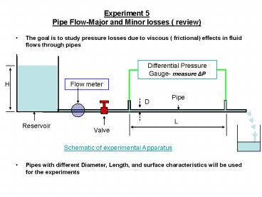
Experiment 5Pipe Flow-Major and Minor losses (
review)
- The goal is to study pressure losses due to
viscous ( frictional) effects in fluid flows
through pipes
Differential Pressure Gauge- measure ?P
Flow meter
Pipe
D
L
Valve
Schematic of experimental Apparatus
- Pipes with different Diameter, Length, and
surface characteristics will be used for the
experiments
2
Major and Minor losses
Total Head Loss( hLT) Major
Loss (hL) Minor Loss (hLM)
Due to sudden expansion, contraction, fittings etc
Due to wall friction
K is loss coefficient must be determined for each
situation
In this experiment you will find friction factor
for various pipes
For Short pipes with multiple fittings, the minor
losses are no longer minor!!
3
Major loss
Differential Pressure Gauge- measure ?P
L
? µ e
V
Pipe
D
- Physical problem is to relate pressure drop to
fluid parameters and pipe geometry
Using dimensional analysis we can show that
4
Friction factor
5
Friction Factor
- For Laminar flow ( Relt2300) inside a horizontal
pipe, friction factor is independent of the
surface roughness.
For Laminar flow
- For Turbulent flow ( Regt4000) it is not possible
to derive analytical expressions. - Empirical expressions relating friction factor,
Reynolds number and relative roughness are
available in literature
6
Friction factor correlations
- f is not related explicitly Re and relative
roughness in this equation. - The following equation can be used instead
7
Moodys chart for friction factor
f
Increases
Laminar f64/Re
Smooth
Transition
ReD
8
(No Transcript)
9
Minor Losses
Valves
Bends
T joints
Expansions
Contractions
- Flow separation and associated viscous effects
will tend to decrease the flow energy and hence
the losses - The phenomenon is fairly complicated. Loss
coefficient K will take care of this
complicities
10
Experiment 5 - New Experimental Set up
11
Experiment 5 - Experimental Steps Details
- Overall Measurements
- Measure the Reservoir Height, H
- Measure the Distances L1, L2, etc.
- Measure the distances ?x1, ?x2, etc. Measure the
pipe diameters
- For EACH PIPE Follow Steps below
- Set the reservoir height, H, to the maximum
level, approx. close to the spill-over
partition height. Record the level. - Adjust the flow rate to a relatively high value,
wait for steady flow to be established. - Measure the flow rate.
- Measure the pressure drop, ?P, for this flow
rate. - Reduce the flow rate, by using the valves, repeat
steps 1 2. - Reduce the reservoir height and repeat steps 1-3.
- Repeat all steps until 3 reservoir heights have
been measured - Hence for each pipe, you will measure ?P, for
six flow rates - (3 H x 2 valve openings)
?x2