
The Analog Feedback Machine Full Schematic - PowerPoint PPT Presentation
1 / 29
Title:
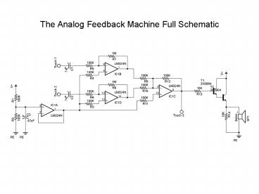
The Analog Feedback Machine Full Schematic
Description:
The Analog Feedback Machine Full Schematic Parts List Water Analogy - How Electricity Moves Electricity Basics - The DC Circuit Electricity Basics - The DC Circuit ... – PowerPoint PPT presentation
Number of Views:1400
Avg rating:3.0/5.0
Title: The Analog Feedback Machine Full Schematic
1
The Analog Feedback Machine Full Schematic
2
Parts List
Part Value Quantity
Resistor 10K 2
Resistor 1M 3
Resistor 100K ohm 10
Resistor 1M ohm 4
Capacitor .1uf 2
Capacitor .47uf 1
Capacitor 220uf-470uf 1
Speaker 8 ohm 1
LM324 / TL084 / TL074 Quad Op Amp 1
Transistor 3904 NPN 2
Battery Clip 9V 1
3
Water Analogy - How Electricity Moves
Voltage Water Pressure - Stored Potential
Energy Current The Amount of water flowing
through an area at a given time. Positive
current convention tracks flow from positive
voltage to negative Electrons flow from negative
to positive.
4
Electricity Basics - The DC Circuit
Battery Lamp Switch
5
Electricity Basics - The DC Circuit
6
Electricity Basics - The DC Circuit
Current flows when the switch is closed.
7
Basic Theory Parts
- Imagine a circuit like a system of pipes and
valves - Battery water pump
- Conductors/Wires main pipes
- Resistors smaller pipes of varying sizes
- Capacitors water balloons
- Transistors valves controlled by water flow
- Integrated Circuits pre-built, super miniature
circuits
8
Parts Symbols
9
Transistors
- Transistors come in many flavors these days.
Bipolar Transistors are semiconductor components
with the three connections - Base, Emitter, and Collector
- A small current flow applied to the Base of the
transistor permits a larger (and proportional)
current flow between the Collector and Emitter - NPN - is active when a positive current relative
to the emitter is applied to its base - PNP - is active when a negative current relative
to its emitter is applied to its base
NPN
PNP
10
Transistors can be used as an electrically
controlled switch!
Applying a positive current to the base of T1 at
5 volts through the 47k ohm resistor causes it to
go into saturation.
11
Transistors can be used to drive LEDS as shown
Applying a positive current to the base of T1 at
5 volts through the 47k ohm resistor causes it to
go into saturation. Current then flows through
R1 and the LED causing it to light.
12
IMPORTANT NOTE!
- Our Transistors have a non-standard pin-out
- From Left to Right (with flat side facing you and
legs pointed down) - Pin 1 EMITTER
- Pin 2 COLLECTOR
- Pin 3 BASE
13
Operational Amplifiers
- Two inputs
- Non-Inverting ()
- Inverting (-)
- Fixed gain factor
- Open loop gain
- Feedback used to control gain and to produce
other useful circuits.
14
Operational Amplifiers
15
(No Transcript)
16
Virtual Ground
- Analog audio signals swing both positive and
negative relative to a fixed voltage. - When powering audio electronics from a battery
supply, a virtual ground reference must be
generated. - This can be done using a voltage divider and a
voltage follower.
17
The Analog Feedback Machine Full Schematic
18
Circuit Breakdown
- Inputs
- Touch Pads (thumb tacks optional)
- Circuits
- Voltage Divider
- Voltage Follower
- Inverting Amplifier
- Summing Amplifier
19
The Analog Feedback Machine Full Schematic
20
(No Transcript)
21
The Analog Feedback Machine Full Schematic
22
(No Transcript)
23
The Analog Feedback Machine Full Schematic
24
(No Transcript)
25
The Analog Feedback Machine Full Schematic
26
Amplifying Signals
27
The Analog Feedback Machine Full Schematic
28
Adding Signals Together
29
Full Schematic
Recommended
CrystalGraphics Presentations


