
Simulation of shaped comb drive - PowerPoint PPT Presentation
1 / 52
Title:
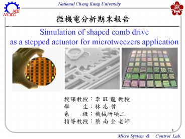
Simulation of shaped comb drive
Description:
Introduction Capacitance ... rectangle Intersection Create rectangles Create composite object Create another rectangle Scale Subdomain Setting for Electrostatics ... – PowerPoint PPT presentation
Number of Views:130
Avg rating:3.0/5.0
Title: Simulation of shaped comb drive
1
?????????
Simulation of shaped comb drive as a stepped
actuator for microtweezers application
????? ? ? ?? ? ?? ? ? ?
?????? ????? ? ? ??
2
Introduction
- Capacitance-based sensors and actuators have been
extensively used in micro electromechanical
systems (MEMS) devices. - The basic design of a comb drive relies on the
theory of parallel-plate capacitors, which in
turn is a function of the plates area and shape.
3
The following model of an electrostatically
actuated comb drive opens and closes a pair of
microtweezer.
4
The following definitions applied to the system
- The material used in the fabrication
(polysilicon) was assumed homogeneous and
isotropic. - The thickness dimension was small compared to the
length. - The stress in the normal Z-direction was ideally
zero.
5
Electromechanical principles of the comb drive
- In the air surrounding the comb drive, the
electrostatic problem is described by Laplaces
equation (in rectangular coordinates)
where
Vpotential energy, which is defined as
6
- The electric energy We is computed at all
elements according to
where
electric field vector, which is defined as
7
- For capacitance C and electrostatic force Fes
where
V0actuation voltage.
8
Modeling in COMSOL Multiphysics
- Because electrostatic forces attract the combs to
each other, and geometric change has an impact on
the electric field between them. To account for
this effect, the model uses an arbitrary
Lagrangian-Eulerian(ALE) method implemented in
COMSOL Multiphysics Moving Mesh application
mode. - In this model the displacements are relatively
large and support for large deformations in the
Plane Stress application mode is used.
9
Modeling
10
Create rectangles
11
Array
12
Union
13
Create another rectangle
14
Intersection
15
Create rectangles
16
Create composite object
17
Create another rectangle
18
Scale
19
Subdomain Setting for Electrostatics
20
Subdomain 1
21
Subdomain 2 , 3
22
Force tab.
COMSOL Multiphysics then automatically generates
the variables Fes_nTx_emes and Fes_nTy_emes for
the electrostatic force components. Later on we
will use these variables to define the boundary
load in the Plane Stress application mode.
23
Boundary Conditions
24
Zero charge/symmetry
25
Continuity
26
Vin
27
Ground
28
Subdomain Setting for Moving Mesh
29
Subdomain 1(Air)
30
Subdomain 2 , 3 (Comb drives)
These are the displacement calculated in Plane
Stress application mode.
31
Boundary Conditions
32
Symmetry
33
Fixed
34
Comb drive
35
Subdomain Setting for Plane Stress
36
Subdomain 1
37
Subdomain 2 , 3
38
Boundary Conditions
39
Symmetry
40
Fixed
41
Free
42
Es force
43
Initialize Mesh
44
Solver Parameters
45
Solver
46
Result
47
(No Transcript)
48
Result
49
(No Transcript)
50
Result
51
(No Transcript)
52
Reference
- Isabelle P. F. Harouche and C. Shafai,
Simulation of shaped comb drive as a stepped
actuator for microtweezers application, Sensors
and Actuators A Physical, 2005. - Michel A. Rosa, Sima Dimitrijev and H. Barry
Harrison, Improved Operation of Micromechanical
Comb-Drive Actuators through the Use of a New
Angled Comb Finger Design, Journal of
Intelligent Material Systems and Structures,
1998, 9, 283
Recommended
CrystalGraphics Presentations


