
Autonomous Parallel Parking Alex Braun - PowerPoint PPT Presentation
1 / 27
Title:
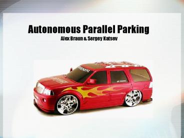
Autonomous Parallel Parking Alex Braun
Description:
Autonomous Parallel Parking Alex Braun & Sergey Katsev Overview Objectives User Interface Algorithms Utilized Hardware Hardware Design Current Status Objectives ... – PowerPoint PPT presentation
Number of Views:328
Avg rating:3.0/5.0
Title: Autonomous Parallel Parking Alex Braun
1
Autonomous Parallel ParkingAlex Braun Sergey
Katsev
2
Overview
- Objectives
- User Interface
- Algorithms
- Utilized Hardware
- Hardware Design
- Current Status
3
Objectives/Performance Specs
- Follow a reflective track
- Receive user commands over a wireless interface
- Leave track and parallel park
- Leave parking space and reacquire track
- Minimum parking space 2 car lengths
- Travel speed .5 1 foot per second
- Capable of following any turns greater than
vehicle turning radius
4
Implementation
- Vehicle
- 112 Scale model of a Lincoln Navigator
- Chassis and drive motor from original RC car
- Steering implemented with Futaba S3003 Servo
motor - Power
- 9.6V rechargeable NiCad battery pack
- Voltage regulators used to provide 5V power to
electronics and isolate power planes
5
User Interface
- Remote control used to issue user commands
- Vehicle responds with actions and LED status
lights - Remote uses 9V battery
6
Remote Design
7
User Interface
- Status lights will indicate
- Current operating mode
- Manual
- Automatic
- Looking for track
- Following track
- Looking for Space
- Parking
- Parked
- Error
- Waiting for user parking override
- Turn Signal
8
Sensor Layout
- IR arrows show direction of beam
- Wireless interface used for remote control user
commands (more later)
9
Algorithms Track Following
- Front sensors used to determine when to turn
- Two turning angles
- Rear sensors used when acquiring the track and
as a backup if all front sensors are lost
10
Algorithms Track Following
11
Algorithms Parking
- Minimum parking spot size 2 car lengths
- Algorithm iterates if can not fit in spot in one
motion
12
Algorithms Parking(Basic Algorithm)
13
Algorithms Parking Space Exit
14
Utilized Hardware
- Processing
- Onboard HCS12
- Sensors
- Track Sensors
- Fairchild QRE00034 Infrared Reflective Sensor
- Used with a comparator to provided digital input
to the HCS12
15
Utilized Hardware
- Speed Sensor
- Fairchild QRE00034 Infrared Reflective Sensor
- Used with a comparator and a shaft encoder to
produce a timer interrupt every quarter
revolution of the rear wheels
16
Sensor Experiment Data (1)
Test Surface
Figure Experiment 1 ? Angle of incidence L
Sensing Distance
17
Sensor Experiment Data (2)
Figure Experiment 2 ? Max viewing angle L
Sensing Distance
18
Utilized Hardware
- Collision Detection
- Sharp GP2D120 Infrared Distance Sensors
- Analog value fed to HCS12 through ADC
- Parking Space Detection
- Sharp GP2D150A Infrared Distance Sensor
- Provides digital detection at 15cm
19
Power Consumption
20
Hardware
- Ribbon cable used to connect HC12 to PCBs
- PCBs stacked to maximize available board space
- Final product will (hopefully) fit inside
original vehicle cover
21
Hardware Drive Electronics
- Motor draws 1.6A max.
- Texas Instruments SN754410 Quad Half H-Bridge
used. - 1A sustained load capacity, 2A peak load (per
half H-bridge) - Two H-bridges used in parallel
H-bridge functional schematic
22
Drive Electronics Design
23
Hardware Wireless Interface
- Ming 4-bit Tx/Rx
- 300MHz AM
- Uses Holtek Encoder and Decoder chips
- Remote contains 74LS922 Key matrix decoder with
debounce protection
24
Receiver Design
25
Hardware Sensor Input Conditioning
- Two quad binary comparator circuits
- Threshold set at 4.0V, established experimentally
- Separate voltage regulator
- Will contain HC12 inputs for all digital sensors
26
Sensor Conditioning Design
27
Costs
28
Current Vehicle Status
29
Current Vehicle Status
Receiver
Rear track sensors
Front Track Sensors
DC Motor
Steering Servo
Comparators
HCS12
H-Bridge
30
Difficulties
- Speed Controller Pseudo Shaft Encoder
- Heat Dissipation May have to place a second
voltage regulator in parallel for drive
electronics - HCS12 operates differently in DBUG12 mode than it
does in LoadEE mode, so tracing code is
practically impossible
31
Testing Methodology
- Unit testing of both software and hardware units
- Unit integration and system-wide testing
- Extensive operation to ensure proper burn-in
- For code Desk Checks by the person who didnt
write the code
32
Track Following Demo
33
Questions?
- Thank you!
Recommended
CrystalGraphics Presentations


