
Shear stress versus shear strain - PowerPoint PPT Presentation
1 / 10
Title:
Shear stress versus shear strain
Description:
Shear stress versus shear strain Shear stress-strain diagram Allowable Stress Designing for allowable stress Shear stress versus shear strain Shear stress-strain ... – PowerPoint PPT presentation
Number of Views:431
Avg rating:3.0/5.0
Title: Shear stress versus shear strain
1
(No Transcript)
2
Shear stress versus shear strain
For homogeneous isotropic materials pure shear
causes angular distortion of a material as shown
above. Pure shear is most often studied by
torsional tests of thin bars. Behavior is
completely analogous to normal stresses.
3
Shear stress-strain diagram
G is shear modulus or modulus of rigidity
4
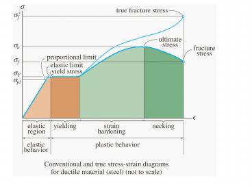
- The shear stress-strain diagram for a titanium
alloy bar tested in torsion is shown in the
Figure. Determine - Shear modulus
- Proportional Limit
- Ultimate stress
- Yield stress
- Fracture stress
5
A bearing pad used to support machines is shown.
The following formulae can be used to determine
shear stress, shear strain and displacement.
For small angles
6
Problem (4) The plastic block shown of 50 mm
depth is bonded to a rigid support and to a
vertical plate to which a 240-kN load P is
applied. Knowing that for the plastic used
G1000 MPa, determine the deflection of the
plate.
Rigid support
Spring 2006 Mid Term Question
7
Problem (4) The plastic block shown of 50 mm
depth is bonded to a rigid support and to a
vertical plate to which a 240-kN load P is
applied. Knowing that for the plastic used
G1000 MPa, determine the deflection of the
plate.
Rigid support
Spring 2006 Mid Term Question
8
Allowable Stress
Factor of safety
F.S.1
F.S.3
9
Designing for allowable stress
Bearing (compression)
Tension
Shear
10
Problem (6) Determine the intensity w of the
maximum distributed load that can be supported by
the hanger assembly so that an allowable shear
stress of ?allow 15 ksi is not exceeded in the
0.40-in.-diameter bolts at A and B, and an
allowable tensile stress of sallow 25 ksi is
not exceeded in the 0.5-in.-diameter rod AB.
Spring 2006 Mid Term Question
Solve at home will cover in help session on
Sept 7th
Recommended
CrystalGraphics Presentations


