
Optotriac - PowerPoint PPT Presentation
1 / 53
Title:
Optotriac
Description:
Virtual Instrumentation. 9/9/09. Robotics Spring 2002. 14. Motor Control. Two approaches ... An example of virtual instrumentation ... – PowerPoint PPT presentation
Number of Views:132
Avg rating:3.0/5.0
Title: Optotriac
1
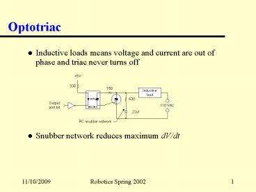
Optotriac
- Inductive loads means voltage and current are out
of phase and triac never turns off - Snubber network reduces maximum dV/dt
2
Digital-to-Analog Conversion
- The real world is ANALOG! Computers are DIGITAL!
- Obviously what is needed is an A/D converter
- D/A converters are easier to build
- Operational amplifiers
- Very high-gain differential amplifier (order of
106 or more) - Inverting and non-inverting inputs
- Very high impedance input very low impedance
output - Use positive and negative feedback to operate
with controlled gain - Produce bi-polar outputs
3
Operational Amplifier
Notice that negative feedback is used
Parameters Slew rate Gain bandwidth Settling
time
4
DAC (Digital-to-Analog Converter)
Where 0 ? V0 ? 4.69
Why not 5 volts?
5
A Few Major Problems ...
- Non-precision reference voltage
- Totem-pole output voltage varies with current
drawn - Need precision binary-weighted resistors
- 4-bit require accuracy to 1 part in 16 (about 6)
- 16-bit requires accuracy to 1 part in 216 (about
.0015) and range of 10 K? to 655.36 M?
6
R-2R Resistor Network
Notice that a constant current flows out of each
switch. Also notice the net resistance to ground
at each point, A-D, is R.
7
Commercial DAC Terminology
- Uni- or bi-polar values
- Double buffering
- Nominally, the inp and outp are for 8-bit values
- Two loads to output a 12- or 16-bit value
- Linearity
- Analog output of an n-bit DAC increases in steps
of 1/2n of the DAC output range - Two forms
- Integral non-linearity
- Differential non-linearity
- Settling time
8
Terminology (Contd)
- Spiking
- Digital ground line
- Analog ground line
- Current output DAC
- Eliminates the costly high-speed op-amp
- Multiplying DAC
- Works with range of reference voltages
- Output is a the product of DACs digital input
and reference voltage - Four-quadrant multiplying DAC
- Handles ? inputs
- Produces ? outputs
9
Analog-to-Digital Conversion (ADC)
- Many different approaches
- Successive approximation
- Dual-slope integrating (based on integrating
charge) - Flash (using simultaneous comparisons)
- Sub-ranging (course then finer resolution of
error) - Delta-Sigma
- Approach related to
- Speed
- Accuracy
- Cost
10
Successive Approximation ADC
11
ADC Performance Issues
- Aliasing
- Nyguist frequency
12
ADC Performance Issues (Contd)
- Antialiasing filter
- Resolution
- Limited dynamic range
- 12-bit ADC with 0-10 volt range accurate to
0.024 (1 part in 4096) - Only 2-bit ADC when sampling a 10 millivolt
signal - Use programmable-gain amplifier
- Non-linear
- Ground reference and noise
13
Data-Acquisition Subsystems
- Typical board
- Contains ADC, DAC, and digital I/O
- Antialiasing filters
- Programmable gain amplifiers
- Sample/hold (one multiplexed or one per channel)
- Single-ended or differential input
- DMA control
- FIFO queues and buffers
- Timer/counters
- Software
- Lab Notebook
- Virtual Instrumentation
14
Motor Control
- Two approaches
- Open-loop
- Closed-loop
- Two types of motors
- Stepper
- Reliable unless acceleration, speed or torque
capabilities exceeded - Wide range from ¼ revolution per step (rps) to
1/2000th rps - Servo
- Cannot be run reliably without feedback
- Based on cheap DC motors
15
Stepper Motor
- Digitally controlled
- Predictable and operated in open loop
- Moves in fixed steps
- Software tracks position
- Mechanically
- Rotor (permanent magnet) and stator
(electromagnet) - Rotor consists of two groups of gear-like teeth,
rotated w/r to each other by 1/2 tooth spacing - Stator is cylinder with teeth
- Runs either clockwise or counter-clockwise based
on stator poles activated
16
Stepper Simplified View
- Each step is 30º or 12 steps/revolution
- Opposing winding are always excited together and
are called a phase - Example is a two-phase stepper
- Another common design is a 1.8? per step,
four-phase hybrid stepper - A bifilar wound stepper motor has two sets of
oppositely wound stator windings and requires
only a single power supply
17
Driving Stepper Motors
- For bifilar wound motors, use L/R driver
- Drive current determined by inductance (L) of
winding and series resistance (R) - Energize the four phases in proper order and for
appropriate amount of time - Single-phase excitation - simplest
- Dual-phase excitation - produces rotor positions
halfway between single-phase steps and offers
most torque and smoothest operation - Half-step excitation - doubles number of steps
- Stepping rate is crucial if steps are not to be
missed
18
L/R Unipolar Drive Circuit
19
H-Bridge L293D
- An integrated circuit that can supply the
necessary voltage/current to the stepper or servo
motor - For a two coil stepper
20
H-Bridge (Contd)
- The enable pins, 1 9, should be tied to 5 to
run the motor all the time - Control pins, 2/7/10/15, are cycled to get the
four phases for a two-phase stepper
21
Connecting to the BS2
- Very simple
- Can have multiple steppers
22
Servo Motors
- Take the form of a permanent-magnet DC brush
motor - Notice the linear speed/torque/current
relationships
23
Servo Motors (Contd)
- Commutator reverses current through rotor as it
turns - Driven by same H-bridge switchers as stepper
motors - Pulse width modulation (PWM) used, as before, to
control voltage/speed without wasting power in
driver circuit - Also comes in brushless version
- Avoids brush wear
- Reverses construction of rotor and stator (built
like stepper) and requires switching current
through stator - Unlike stepper, there are not teeth on rotor put
rotor position sensor is need - Generates more torque than a stepper at high
speeds
24
Motor Position Sensor
- Several choices
- Optical encoder
- Incremental uses an encoding disk and counter
- Quadrature uses two encoding disks to counter
(one to count input and the other to clock input) - Can sense direction and know absolute count
- Basis for modern mice
- Neither tells initial position
- Normally drive servo to one end of travel limit
which causes a limit switch to be activated - Absolute encoder
- Contains multiple concentric tracks to provide
absolute position within one revolution - Often uses Gray code (e.g., 000, 001, 011, 010,
110, 111, 101, 100, 000, )
25
Driving Two DC-Motors
- Can use the same L293D for this but now it will
control two motors
26
Closed-Loop Motor Control
User Commands
Motor Shaft
Digital Controller
Shaft Position Sensor
Motor Driver
Motor Control Signals
Motor
Load
Shaft Position Feedback
27
PID
- Proportional, Integral, and Derivative control
algorithm - Where
- First term is proportional to error signal but
- Second term provides sum of error terms
- Third term offers damping as error grows smaller
28
PID Block Diagram
29
LabVIEW
- An example of virtual instrumentation
- Consists of a computer, software, and data
acquisition (DAQ) hardware - LabVIEW provides
- Enhanced functionality over traditional system
through graphical interface - User does not write software in traditional
fashion (using assembly or C languages) - DAQ is data not control flow driven
30
LabVIEW (Contd)
- Front panel is the window through which the user
interacts with the VI program - Must always have front panel window open
- View inputs and output on the front panel
- Front panel made up of controls (knobs and
switches0 and indicators (numeric and graphical
displays) - Drag and drop controls from controls palette
- Source code of the VI is held in the block
diagram (using functions palette) - Made up of terminals, nodes, and wires
- Terminal - associated with control on front panel
- Node - program execution element
- Wires - connect nodes and terminals (extensive
error checking)
31
Simple LabVIEW Example
Control terminal
Wire
Indicator terminal
Node
32
Digital Thermometer
- Front panel
But what does the VI block diagram look like?
33
Other Features
- Rich data structures
- For and While loops
- Shift registers and initializing shift registers
- Sequencing
- Case Structures
- Formulas
- Arrays and clusters
- Operators
- Polymorphism and compound arithmetic
- Display types
- Indicators
- Graphs and charts
34
Features (Contd)
- Instrument simulation
- I/O
- Strings
- File handling
- Many debugging techniques
- Breakpoints
- Single stepping
- Probes
- Reference Learning with LabVIEW 6i, Robert H.
Bishop, Prentice Hall, ISBN 0-13-032559-7
35
The Software Life Cycle - Chapter 4
- Engineering approach
- Specification, design, construction, testing, and
maintenance - IEEE Std 830 for specification
- DOD-STD-2167A for software development
- Software life cycle phase
- Concept
- Requirements
- Design
- Programming
- Test
- Maintenance
Relate to our programming projects
36
Concept
- Purpose
- Define project needs and goals
- Produce a white paper or operational concept
document - No...
- formal requirement stated
- hardware/software decisions made
- budgets and schedules are set
- Identify product need and goals
- Produce feasibility studies
37
Requirements
- Decide what the product must do
- Documentation prepared by customer
- What the product does
- Timing, UI, accuracy, etc. specified
- May include schedule and budget
- Testing determined and committed (e.g., formal
test plan) - Functional and non-functional requirements (e.g.,
what can and cannot be tested) - Functional fire alarm sounds within 2 seconds of
smoke detection - Non-functional programmed in C
38
Requirements (Contd)
- Documentation rules
- Must be complete
- Must be correct
- Must be consistent
- Every requirement or design element should be
testable
39
Design
- Shows how the product will meet the requirements
- Converts requirement into detailed design
- Provides partitioning of the functional features
into software and hardware modules - Prepare test cases
- Helps identify conflicts, redundancies, or
impossible requirements - Implementation details hidden by using ADTs and
objects
40
Programming
- Write and debug the software (easy!)
- Fills in details missing in design phase
- Enhanced by tools
- Debuggers
- Version control software
- Simulators
- Code generators
41
Testing
- Verify requirements are met
- Quality assurance
- Automated test generators
42
Maintenance
- Begins after verification
- Product deployment
- Customer support
- Error reporting
- Product enhancement
43
Universal Real-Time Operating System
- Intimately familiar with this RTOS
- Has all the usual components
- Kernel with processes and threads
- Communicates with other units (IPC)
- Can be scheduled and interrupted
- Uses memory management, monitors actions, and
performs error correction - Exhibits protection and fault isolation/repair
44
State of the Field
- Real-time systems
- Must meet timing constraints
- Must produce correct result within a specified
time - Late (and possibly early) actions are useless or
harmful - Not simply a function of increasing system
throughput - Requires timeliness and predictability
- Do not have to be fast systems
- Hard real-time
- Critical deadlines to be met
- Soft real-time
- Non-critical deadlines
45
Basic Real-Time Concepts
- Engineering black box approach
- Definition A system has a set of one or more
inputs entering a black box and a set of one or
more outputs exiting the black box - The internal process by which inputs are
converted to outputs is called the transfer
function - Definition The time between the appearance of an
input and an associated output is call the
response time of the system
I1 . . In
O1 . . On
46
Real-Time Definitions
- Definition A real-time system is a system that
must satisfy explicit (bounded) response time
constraints or risk severe consequences,
including failure - Definition A failed system is a system that
cannot satisfy one or more of the requirements
stipulated in the formal system specification - Definition A real-time system is one whose
logical correctness is based on both the
correctness of the outputs and their timeliness - Definition A reactive system is one that has an
ongoing interaction with its environment
47
Real-Time Definitions (Contd)
- Definition An embedded system is one where the
specialized control hardware includes the
computer - Bottom line
- All practical systems can be said to be
real-time! - Response time for some systems is days or even
weeks (what we called soft real-time systems)
48
Other Terms and Definitions
- Definition An event is said to be synchronous if
it always occurs at the same time and place
otherwise, it is said to be an asynchronous event - Definition A system is said to be deterministic
if, for each possible state and set of inputs, a
unique set of outputs and next state of the
system is known
49
Real-Time Kernels
- Three functions provided
- Task scheduling (scheduler)
- Task dispatching (dispatcher)
- Intertask communications
- Task and process used interchangeably
- Multi-Level Interpretive or layered system
- Applications level
- Programming language level
- Run-time environment
- Operating system level
- Native machine level
- Hardware systems
50
Kernel or Nucleus
51
Reliability - Chapter 11
- For a given system S which fails at time T, the
reliability of S at time t, denoted r(t), is the
probability that T is greater than t, that is - Failure function is the probability that the
system fails at time t - We commonly accept the bathtub curve as a
standard model
52
Fault Tolerance
- The ability of the system to continue to function
in the presence of hardware or software failures - Spatial redundancy
- Methods involving redundant hardware or software
- Involves
- Voting
- Checkpointing
- Recovery blocks
- N-version programming
- Built in testing (CPU, memory, etc.)
- Temporal redundancy
- Techniques that allow for tolerating missed
deadlines - Hardest of the two to achieve
53
Summary
- This last day has included a great many topics,
from computer interfaces and motor controls, to
software development, and real-time systems - As will all topics, there are the fun parts that
include building and testing, and the more formal
parts that result in reliable software and
hardware - Students must learn not only the skills and
techniques but the basic principles that lead to
newer and better robots/controllers
Recommended
CrystalGraphics Presentations


