
Failure Theories - PowerPoint PPT Presentation
1 / 20
Title:
Failure Theories
Description:
... middle portion of the rod, if it is to be made from AISI 1040-hot rolled steel. ... properties similar to AISI 1020 hot-rolled steel. Use a design factor ... – PowerPoint PPT presentation
Number of Views:88
Avg rating:3.0/5.0
Title: Failure Theories
1
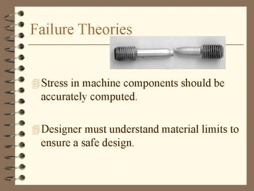
Failure Theories
- Stress in machine components should be accurately
computed. - Designer must understand material limits to
ensure a safe design.
2
Design Factor
- Factor of Safety (N)
- Suitable values depend on inherent danger,
certainty of calculations, certainty of material
properties, etc.
3
Static Stresses - Brittle Materials
- Percent elongation lt 5
- for parts in tension
- for parts in compression
- for parts with general stress
4
Example
- The Gray Cast Iron (Grade 40) cylinder carries an
axial compressive load of 75,000 lbs and a torque
of 20,000 in lbs. Compute the resulting design
factor.
5
Static Stresses - Ductile Materials
- Percent elongation gt 5
- Distortion Energy Theory
- Define von Mises Stress
- For nominal stress
- For localized stress
6
Static Stresses - Ductile Materials
- Percent elongation gt 5
- Maximum Shear Stress Theory
- For nominal stress
- For localized stress
7
Example
- Specify a diameter for the middle portion of the
rod, if it is to be made from AISI 1040-hot
rolled steel.
8
Example
- For the seat support shown, specify a standard
structural tube to resist static loads shown. The
tube has properties similar to AISI 1020
hot-rolled steel. Use a design factor of 3.
9
Repeated Loads
10
Example
- The notched bar is machined from AISI 1020 steel.
This bar is subjected to a load that varies from
2000 lb to 3000 lb. Determine the mean and
alternating nominal stresses.
11
Fatigue Strength
- R.R. Moore Test
12
Endurance Strength
- sn Endurance strength
- Listed in tables
- If no information is available, use
- sn ? 0.5 su (Steel)
- sn ? 0.4 su (Aluminum)
13
Adjusted Endurance Strength
- The data from the standard R.R. Moore test is
adjusted for a particular application. - sn Adjusted endurance strength
- (Cs) (Cm) (Cst) (CR) (sn)
14
Size and Stress Type Factors
- Cs Size Factor
- Dlt 0.4 in Cs 1.0
- 0.4 lt D 2.0 in Cs (D/0.3)-0.068
- 2.0 lt D 10.0 in Cs D-0.19
- For rectangular sections, D.808(h b)1/2
- Cst Stress Type Factor
- 1.0 for bending
- 0.80 for axial tension
- 0.50 for torsion
15
Material and Reliability Factor
- Cm Material Factor
- 1.0 for wrought steel
- 0.80 for cast steel
- 0.70 for cast iron
- CR Reliability Factor
- 50 CR 1.0
- 90 CR 0.90
- 99 CR 0.81
- 99.9 CR 0.75
16
Example
- The notched bar is machined from AISI 1020 steel.
This bar is subjected to a load that varies from
2000 lb to 3000 lb. Determine the endurance limit
of the material.
17
Repeated Stresses - Ductile Materials
- Distortion Energy Theory
- Define repeated von Mises Stress
- Solderberg criterion
18
Repeated Stresses - Ductile Materials
- Maximum Shear Stress Theory
- ssy 0.5 sy
- ssn 0.5 sn
19
Example
- The notched bar is machined from AISI 1020 steel.
This bar is subjected to a load that varies from
2000 lb to 3000 lb. Comment on the robustness of
the design.
20
Example
- Comment on the robustness of a 1-1/4 round bar
made from AISI 1213 C-D steel. It carries a
constant tensile load of 1500 lbs, a bending load
that varies from 0 to 800 lbs at the senter of
the 48 length and a constant torque of 1200 in
lbs.