
ECAL prototype CALICE collaboration - PowerPoint PPT Presentation
1 / 14
Title:
ECAL prototype CALICE collaboration
Description:
The tilt angle could move from 0 to 100 mrad (2 possibles positions) ... Only one rotative table for ECAL and for HCAL. 2. ECAL prototype. 2.1 ECAL Modules ... – PowerPoint PPT presentation
Number of Views:28
Avg rating:3.0/5.0
Title: ECAL prototype CALICE collaboration
1
ECAL prototype CALICE collaboration from
mechanical point of view
A.Busata , LPNHE-X
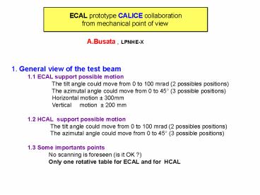
1. General view of the test beam 1.1
ECAL support possible motion
The tilt angle could move from 0 to 100 mrad
(2 possibles positions)
The azimutal angle could move from 0 to 45 (3
possible positions)
Horizontal motion 300mm
Vertical motion 200 mm 1.2
HCAL support possible motion
The tilt angle could move from 0 to 100 mrad
(2 possibles positions)
The azimutal angle could move from 0 to 45 (3
possible positions) 1.3 Some
importants points No
scanning is foreseen (is it OK ?)
Only one rotative table for ECAL and for
HCAL
2
2. ECAL prototype 2.1 ECAL Modules
gt General definition tungsten-silicon
samplingcalorimeter with 3 modules
using different tungsten thickness
gt The general structure is made of tungsten
-fiber (half of the tungsten) the
second half is used for the detector slab.
gt The 3 modules are
module 1 10 layers ( W1.4mm Si 0.525
mm) 4X0 module 2 10
layers ( W2.8mm Si 0.525 mm) 8X0
module 3 10 layers ( W4.2mm Si
0.525 mm) 12X0 2.2 ECAL mechanical
structure gt there is 3 structures with
alveola monoblocs W compiste FC/epoxy resin
tungsten 1.4, 2.8 , 4.2 mm x 124.5
mm x 376.6 mm composite FC
prepreg. (carbon fiber) 0.15mm gt Each
module contains 3 aveolas for each layer.(2 of
them will equiped with silicon
wafers, 1 will be used for CEM test of the SiSC.
3
3. Technological prototype 3.1 Prototype
bitube'' (carbon fiber enveloppe of the
detector slab) 3.2 Prototype SiSC''
(Silicon Support Circuit) 3.3 Prototype
modules detector A and B gt Module type
A type central aveola gt Module type B
type lower aveola gt Remember that
upper alveola is dedicated to test in real
condition of e.m. noise and leakage
current. (i.e. CEM test of the Readout
Kapton,etc..) 4. Schedule for the technological
RD Proto.
deadline 4.1
Prototype bitube''
15/04/02 4.2 Prototype
kapton readout circuit
30/03/02 4.3 Prototype SiSC''
15/05/02
4.4 Integration module A, B
01/11/02 4.5 Integration
module 1
01/10/02 4.6 Cosmics test of module 1
31/12/02 5.
Schedule for the physics prototype
Item
deadline 5.1 Integration all
module
31/12/03 5.2 Test beam with HCAL
31/06/04
4
(No Transcript)
5
(No Transcript)
6
(No Transcript)
7
(No Transcript)
8
(No Transcript)
9
(No Transcript)
10
(No Transcript)
11
Detector slab
12
(No Transcript)
13
(No Transcript)
14
SiSC
Recommended
CrystalGraphics Presentations


